background image

LNW-4

LNW 4 Manual Version 6.5 effective 1 Febuary 2007

Table Of Contents

Important Notice ..................................................................................................... ii

Caution ................................................................................................................. iii

Introduction & Description ...................................................................................... 1

Principle of Operation
Pressure Transducer
Digital Indication
Power Requirements

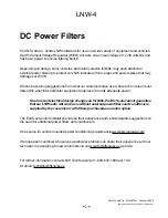
DC Power Filters ................................................................................................... 2

Installation .............................................................................................................. 3

Lift Truck Conditions
Indicator Installation
Hose Installation

Installation Diagram ............................................................................................... 4

Operation ............................................................................................................... 5

Weighing Reference Point
First Stage Cylinder
Weighing Height
Repeatability is the Key to Good Weighing
Description of Controls - ON/OFF, ZERO, ADD/PRINT

Operation (cont.) - Weighing .................................................................................. 6

Set ZERO
To Weigh
Display/Hold
Options; Setpoint, Print

Calibration Procedure ................................................................................ 7& 8 & 9

Check ZERO and Span
Set span
Return to Normal weighing and check Span

Troubleshooting ................................................................................................... 10

Installable Options ................................................................................................ 11

Case Dimensions ................................................................................................ 12

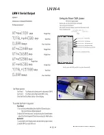
Serial Output & Printer features ............................................................................ 13

Warranty .............................................................................................................. 14

Parts List (partial)................................................................................................. 15

Main Board Diagram ........................................................................................... 16

Wiring connections
Switch settings

Countby (Graduation size - Set to Truck Capacity)
Zero Reset Range

Reset Processor and store Defaults

 i 

Summary of Contents for LIFT-N-WEIGH LNW-4

Page 1: ...LIFT N WEIGH LIFT TRUCK SCALE Pacific Scale Co Clackamas Oregon LNW 4 ON OFF SWITCH ZERO BUTTON ACCUMULATE PRINT OPTION FRONT KEY CALIBRATION OVERLOAD SETPOINT WARNING OPTION RS232 INTERFACE OPTION ...

Page 2: ...ale is installed on a different truck it can be re calibrated in the field A 6 foot high pressure hose and DC wiring harness are included We do not furnish the Tee fitting to connect to your hydraulic lines SPECIFICATIONS CAPACITIES To match the vehicle up to 199 000 lbs DISPLAY 6 digit liquid crystal display height of numbers 0 70 backlit for high visibility POWER 12 volt D C to 50 volt D C See N...

Page 3: ...age Cylinder Weighing Height Repeatability is the Key to Good Weighing Description of Controls ON OFF ZERO ADD PRINT Operation cont Weighing 6 Set ZERO To Weigh Display Hold Options Setpoint Print Calibration Procedure 7 8 9 Check ZERO and Span Set span Return to Normal weighing and check Span Troubleshooting 10 Installable Options 11 Case Dimensions 12 Serial Output Printer features 13 Warranty 1...

Page 4: ...ting on page 9 before attempting to re calibrate the indicator Do NOT spend over 30 minutes in testing and adjusting If you spend more time than this or are having problems Please call for technical assistance 1 800 537 1886 If you call please have available 1 LNW Indicator Serial number ____________ 2 Make Truck ____________ 3 Lift capacity of the vehicle____________ 4 Number of Lift cylinders___...

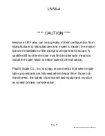
Page 5: ...ons for installation of the indicator are general in scope A qualified lift truck technician may find an alternate means to install the scale which is better suited to the situation Pacific Scale Co Inc strongly recommends that when instal lation procedures are followed which depart from those out lined herein the safety of personnel and equipment must be accorded primary consideration iii ...

Page 6: ...echnology to achieve a high degree of accuracy on the test bench This however is downgraded by the friction and slight differences in psi during the lifting cycle in the lift truck The load on the forks is displayed on a backlighted liquid crystal display for easy viewing in both bright and poorly lighted situations Housing A heavy cast aluminum housing helps protect the indicator against mechanic...

Page 7: ...nt requires to provide adequate power Due to recent electrical design changes on forklifts Pacific Scale cannot guarantee that our LNW units will work as is without external power filters and conditioners supplied by the customer or with filters purchased as an extra option The End User and or Installer should use their experience and vehicle dealers suggestions on the need for additional power fi...

Page 8: ...own voltage converter and or power filters as long as the LNW unit is supplied with clean DC power HOSE INSTALLATION The LNW 4 comes standard with a 6 hose Custom lengths are available One end of the hose is connected between the lift valve and the primary lift cylinder s The Indicator has the second end of the hose connected to the fitting on the back Locate the indicator so the hose and the elec...

Page 9: ... own ON OFF switch and fuse 2 If the lift truck has twin lift cylinders be SURE that the hydraulic connection to the LNW 4 is plumbed into the system so it sees the pressure from the two 2 lift cylinders 3 If the lift truck has three 3 cylinders be SURE that the hydraulic connection to the LNW 4 is plumbed into the cylinder doing the lifting in the first stage This is usually the Freelift cylinder...

Page 10: ...truck capacity e g 100 Lbs on a 5 000 Lbs capacity truck Do NOT keep setting ZERO if it repeats within the 2 range Pickup a load in the same manner and see if it repeats within the range of 2 of truck capacity If Display repeats with the 2 range but the weight is wrong go to the Calibration page and follow the instructions Pages 6 7 8 Note 16 is mentioned as a convenient weighing height If repeata...

Page 11: ...ion in the system This is why jogging down the load is usually required Watch for a pause point that is repeatable for the point to press the ADD PRINT button Clear Total 5 To CLEAR the ADD Total lower load until display is at or near ZERO Press and hold ADD PRINT button and press and release the ZERO button Check Zero during the day 6 Recheck your ZERO occasionally during use Reset ZERO if it has...

Page 12: ...n 2 proceed to Step 2 If the empty weight readings DO NOT repeat within 2 tolerance try lifting the forks to the weighing height 16 to 20 and take your readings as soon as you release the lift valve do not lower Try any method that will give you repeatable readings within the 2 tolerance Step 2 Check Span Lift a known weight equal to approximately 1 2 of lift truck capacity or more Raise the load ...

Page 13: ...al load Note When Display Hold Mode is enabled you must press the ADD PRINT Green button first to freeze the scale reading Otherwise pressing the Zero Red button first will Zero the scale Pressing the ADD PRINT green button will increase the displayed reading Pressing the ZERO red button will decrease the displayed reading While adjusting displayed weight reading to match actual weight you can inc...

Page 14: ...isplay Hold in regular use turn off now To disable Display Hold first turn unit off Press and hold the ZERO Red button while turning power on Display will then flash showing a P and some numbers If there are dashes alternating with the P xxx then Display Hold is Off Press both of the front panel buttons at the same time to toggle Display Hold on and off see page 6 REMEMBER Repeatability consistenc...

Page 15: ...edure Inconsistent Zero setting Leaking Hoist cylinder Air in hydraulic system Mast not upright Hoist cylinder fluid low Mast slides dirty Mechanical system worn bent Friction in cylinder rollers slides etc Follow recommended method Follow proper procedure Repair Bleed system Weigh Zero w Mast upright Add proper amount of fluid Clean lubricate Repair as required Lubricate mastparts be sure load on...

Page 16: ...l system with a Three 3 pin receptacle rubber boot cable clamp Internal wiring for wiring a 10A SPDT relay to the output receptacle NO NC COM matching Three 3 pin cable connector rubber boot cable clamp Dual Calibration Provides the ability to calibrate the LNW 4 in two 2 separate lift cylinder stages e g The operator could obtain a weight in the 1st stage low to the ground and in the 3rd stage hi...

Page 17: ...LNW 4 LNW 4 Manual Version 6 5 effective 1 Febuary 2007 12 ...

Page 18: ...LNW 4 LNW 4 Manual Version 6 5 effective 1 Febuary 2007 13 ...

Page 19: ... of shipment from Pacific Scale Co Inc and is subject to the following limitations Limitations This warranty shall not apply to a Damage which in the opinion of Pacific Scale Co Inc is the result of overloading misuse water damage negligence alteration accident or service performed by other than Pacific Scale Co Inc authorized personnel b The replacement of expendable or consumable parts c Normal ...

Page 20: ...itting 360 Deg swivel ell 1 LC PT FS Main Board 1 L4 MB ON OFF Power Switch toggle only 1 L4 PS ASSY ON OFF Power Switch Boot 1 LC SW B Power Cord Assy 1 LC PC ASSY Install Kit Includes Power Cord Scotchlok taps Bolts Nuts and misc 1 L4 Install Kit Pressure Transducer 1 LC PT Program Chip Latest Std version PRO92F Feb 2003 1 L4 PG F Top Cover w Gasket 1 L4 HT ASSY Top Cover Screws 4 L4 SZ U Bracke...

Page 21: ...LNW 4 LNW 4 Manual Version 6 5 effective 1 Febuary 2007 16 For AD 621 0033 I42472 TL072CP CKVQ 9903 ...

Reviews: