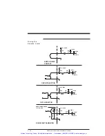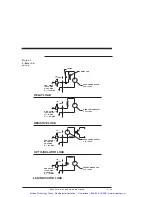
Procedure
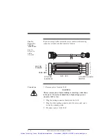
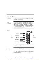
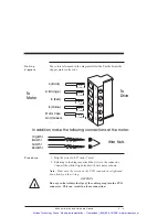
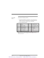
1. Strip the wires 0.27 inch (7 mm).
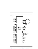
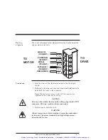
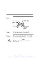
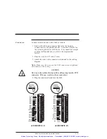
2. Attach the wires to the connector as indicated in the diagram.
Note: Make sure the screws on the PCD connector are
tightened down firmly on the wiring.
CAUTION
Do not pre-tin (solder) the tips of the cables going into the PCD
connector. This can result in a loose connection.
WARNING
The chassis ground must be tied to earth ground. Failure to do
this leaves the potential for severe hazard. Make sure the
ground is connected via the ground stud on the front of the
5645.
3. Plug the mating connector firmly into the 5645.
2.5.3 J3 Serial I/O Connections
Introduction
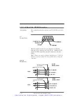
The serial port transmits and receives RS-232 or
RS485-multidrop serial communication for the user interface of
your unit. You can configure to control single or multiple 5645s.
Single- and
multi-unit
control
For controlling a single 5645, use RS-232 communications.
DIP switch S2 must be set to Address 31 for RS-232
Communications as described in Section 2.6.2.
For controlling multiple 5645s, RS-422 or RS-485
communications permits a single PC to host from 1 to 31
5645s (each requiring a unique address ranging from 0 to 30,
set using DIP switch S2 as described in Section 2.6.2).
The 5645 utilizes 9600 baud communications with one start
bit/one stop bit and eight bit word length in either RS-232 or
multidrop format.
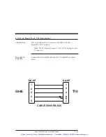
For controlling a single 5645 from a T10 terminal, use
RS-232 communications and install cabling as described in
section 2.5.3.3, “J3 Serial Port - T10 Connection.”
5645 Installation and Hardware Manual
2 - 19
Artisan Technology Group - Quality Instrumentation ... Guaranteed | (888) 88-SOURCE | www.artisantg.com


