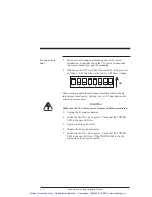
Mating
connector
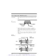
The J6 discrete I/O cables are for a PCD 9-pin screw mating
connector. The connector, supplied with the unit, is ELFH09110.
Cable
requirements
Use 22- to 14-gauge wire for the cabling.
CAUTION
To avoid ground loops, connect ground shield to user interface
only.
Procedure
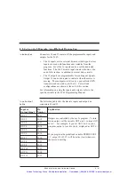
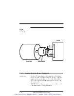
Connect the encoder or step and direction inputs to the 5345/5445
as follows:
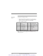
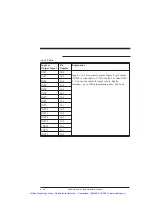
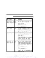
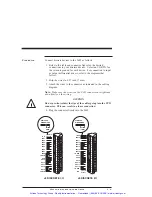
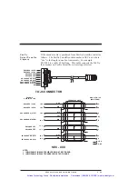
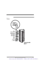
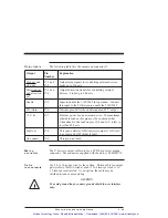
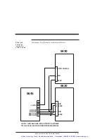
1. Refer to the table and connector figure for the desired input
connections. Connect the +5 RTN if using the +5 V dc for
the encoder.
2. Strip the wires to 0.27 inch (7 mm).
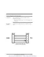
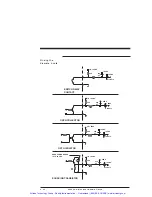
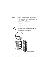
3. Attach the wires to the connector as indicated in the cabling
diagram.
Note: Make sure the screws on the PCD connector are tightened
down firmly on the wiring.
CAUTION
Do not pre-tin (solder) the tips of the cables going into the PCD
connector. This can result in a loose connection.
4. Plug the connector firmly into the 5645.
2 - 36
5645 Installation and Hardware Manual
Artisan Technology Group - Quality Instrumentation ... Guaranteed | (888) 88-SOURCE | www.artisantg.com

