2.5.2 J2 Power Con nec tor
Introduction
The J2 power cable connects the 6410 to the power supply. Please
refer to Appendix C for additional information on power supply
considerations.
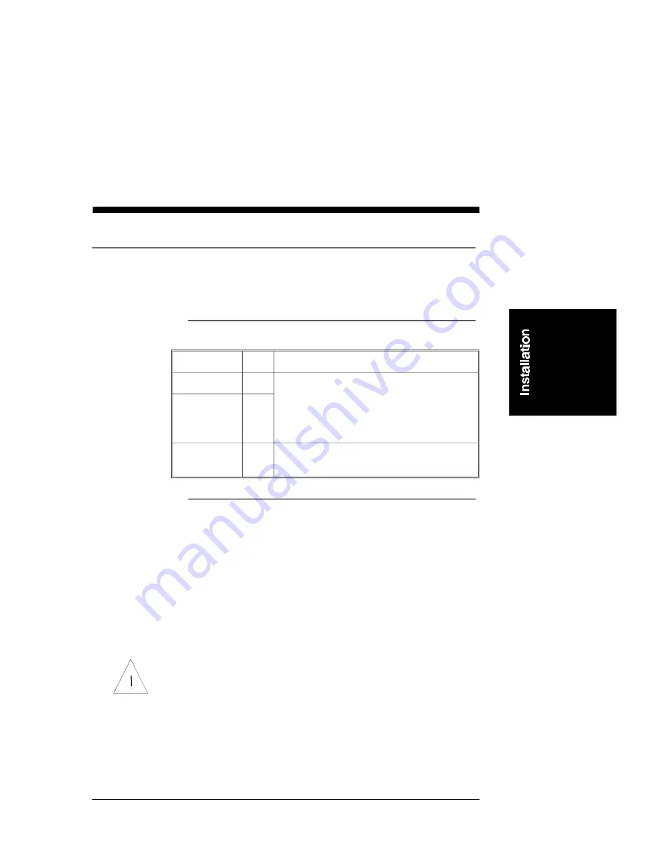
J2 power table
Input
Pin
Explanation
DC -
J2-1
+24 to +75 Vdc max at 5 amps
The negative side of the power supply
(connected to DC-) should be connected to
Earth ground. No connection is made within
the 6410 between J2-1 and J2-3.
DC +
J2-2
Earth Ground
J2-3
Connected to 6410 Case and J3-5 (Motor
Ground)
Power
connection
Connections between the 6410 and power supply are shown in the
diagram on the following page. A simple non-regulated supply is
used for this example. DC+ and DC- should be run from the
power supply’s capacitor to the 6410 as a twisted pair no longer
than 3 feet in length (shielding, with the shield connected to earth
ground, can reduce noise emissions). A Buss MDA 10 A,
slow-blow fuse (or equivalent) should be included in the power
supply between the rectifier and capacitor as shown.
IMPORTANT NOTE
It is extremely important that the supply voltage never exceed 75
volts even on a transient basis. This is one of the most common
causes of drive failures. Wiring inductance between the 6410
power input and the external capacitor is significant because a
PWM chopper drive requires pulse currents. Therefore, it is
extremely important that the two be connected by a twisted pair
no longer than three feet in length.
6410 Installation and Hardware Reference Manual - Rev E
2 - 17
StockCheck.com


