SECTION 1 GENERAL
5
1.3
GENERAL PRODUCT DESCRIPTION
The AMX-Series Power Source is high-performance AC power conversion equipment. This series of
equipment features models with power ratings from 500 VA to 12 kVA. All systems are designed to fit into the
standard 19 inch rack. These systems are suitable for use as frequency changers as well as sophisticated test
power generators.
All systems are configured with an interchangeable controller. Controller options range from the basic manual
type (UMC-Series) to the sophisticated programmable controller (UPC-Series). The manual controller allows
the user to adjust voltage and frequency. The programmable controller, on the other hand, not only allows
control of voltage and frequency, but also allows the user to simulate virtually any transient (including sub-
cycle waveform disturbance) required for testing today's modern electronic equipment.
The standard output voltage range of the AMX-Series is 0-135 VAC
l-n
(0-150 VAC
l-n
for the Model 125-AMX).
Additionally, the Models 112-AMX and 312-AMX can be configured for several output voltage ranges
between and including 0-110 VAC
l-n
and 0-150 VAC
l-n
. Optional output transformers are available to provide
higher voltages. Voltage ratios up to 2.5:1 are available.
The AMX-Series consists of the basic models listed below:
1.
Model 105-AMX
- 500 VA Chassis capable of 1 or 2 Phase operation. Standard
Output voltage range is 0-135 VAC
l-n
, 1
φ
or 0-270 VAC, 2 Phase. Phase separation fixed at 180
°
when operating in 2 Phase Mode.
2.
Model 108-AMX
- Same as 105-AMX, but rated for 750 VA output power.
3.
Model 112-AMX
- Same as 105-AMX, but rated for 1.2 kVA output power. Standard
Output voltage ranges are 0-110 VAC
l-n
through 0-150 VAC
l-n
, 1
φ
or 0-220 VAC through 0-300 VAC,
2 Phase.
4.
Model 125-AMX
- Same as 105-AMX, but rated for 2.5 kVA output power. Standard
Output voltage range is 0-150 VAC
l-n
, 1
φ
or 0-300 VAC, 2 Phase.
5.
Model 140-AMX
- Same as 105-AMX, but rated for 4.0 kVA output power.
6.
Model 160-AMX
- Same as 105-AMX, but rated for 6.0 kVA output power.
7.
Model 305-AMX
- 500 VA Chassis capable of 1, 2, or 3 Phase operation. Standard
Output voltage range is 0-135 VAC
l-n
. Phase separation fixed at 180
°
when operating in 2 Phase
Mode. In 3 Phase Mode, phase separation is fixed at 120
°
or programmable.
8.
Model 308-AMX
- Same as 305-AMX, but rated for 750 VA output power.
9.
Model 312-AMX
- Same as 305-AMX, but rated for 1.2 kVA output power. Standard
Output voltage ranges are 0-110 VAC
l-n
through 0-150 VAC
l-n
, 1
φ
or 0-220 VAC through 0-300 VAC,
2 Phase.
10.
Model 320-AMX
- Same as 305-AMX, but rated for 2.25 kVA output power.
Summary of Contents for AMX series
Page 1: ......
Page 2: ......
Page 10: ......
Page 11: ......
Page 15: ......
Page 16: ......
Page 19: ...SECTION 2 SPECIFICATIONS 9B THIS PAGE INTENTIONALLY BLANK...
Page 21: ......
Page 22: ......
Page 23: ......
Page 25: ......
Page 26: ......
Page 27: ......
Page 28: ......
Page 29: ......
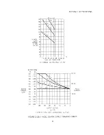
Page 30: ...SECTION 2 SPECIFICATIONS 19A FIGURE 2 1 2 E2 MODEL 160 AMX OUTPUT DERATING CURVES...
Page 31: ...SECTION 2 SPECIFICATIONS 19B THIS PAGE INTENTIONALLY BLANK...
Page 32: ......
Page 33: ......
Page 34: ......
Page 35: ......
Page 36: ......
Page 37: ......
Page 38: ......
Page 39: ......
Page 40: ......
Page 41: ......
Page 42: ......
Page 45: ...SECTION 2 SPECIFICATIONS 31B THIS PAGE INTENTIONALLY BLANK...
Page 46: ......
Page 47: ......
Page 48: ......
Page 49: ......
Page 50: ...SECTION 2 SPECIFICATIONS 36 FIGURE 2 2 3 OUTLINE DRAWING MODELS 125 140 160 345 360 AMX...
Page 51: ......
Page 56: ......
Page 57: ......
Page 58: ......
Page 59: ......
Page 60: ......
Page 61: ......
Page 62: ......
Page 63: ......
Page 64: ......
Page 65: ......
Page 66: ......
Page 67: ......
Page 70: ......
Page 71: ......
Page 72: ......
Page 73: ......
Page 74: ......
Page 75: ......
Page 76: ......
Page 77: ......
Page 80: ...SECTION 3 INSTALLATION 66 FIGURE 3 3 8 AMX SERIES INPUT WIRING DIAGRAM...
Page 82: ...SECTION 3 INSTALLATION 68 FIGURE 3 4 1 1 SINGLE PHASE OUTPUT CONNECTION...
Page 83: ......
Page 84: ......
Page 85: ......
Page 86: ...SECTION 3 INSTALLATION 72 FIGURE 3 4 2 1 SPLIT PHASE OUTPUT CONNECTION...
Page 87: ......
Page 88: ......
Page 89: ......
Page 90: ......
Page 91: ......
Page 92: ......
Page 93: ......
Page 94: ......
Page 95: ......
Page 96: ......
Page 97: ......
Page 99: ......
Page 100: ......
Page 101: ......
Page 102: ......
Page 104: ......
Page 105: ......
Page 106: ......
Page 107: ......
Page 108: ......
Page 109: ......
Page 110: ......
Page 112: ......
Page 114: ......
Page 116: ......
Page 117: ......
Page 118: ......
Page 120: ......
Page 121: ......
Page 122: ......
Page 124: ...SECTION 7 SERVICE 108B THIS PAGE INTENTIONALLY LEFT BLANK...
Page 125: ......
Page 126: ......
Page 127: ......
Page 128: ......
Page 129: ......
Page 130: ......
Page 131: ......
Page 132: ......
Page 133: ......
Page 134: ......
Page 135: ......
Page 136: ......
Page 137: ......
Page 138: ......
Page 139: ......
Page 140: ......
Page 141: ......
Page 142: ......
Page 143: ......
Page 144: ......
Page 145: ......
Page 146: ......
Page 147: ......
Page 149: ......
Page 150: ......
Page 151: ......
Page 152: ......
Page 159: ......


