E - 3
WAS:
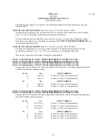
“This paragraph describes the configuration of the Output Voltage Range for the Models 140, 160,
345, 360, 390, and 3120-AMX Power Sources. … A Magnetics Module ( Assembly No. 134310) is
required for the 204, 273 and 341 VAC output forms.”
IS:
“This paragraph describes the configuration of the Output Voltage Range for the Models 140, 160,
320
, 345, 360, 390, and 3120-AMX Power Sources. … A Magnetics Module ( Assembly No.
134350
)
is required for the 204, 273 and 341 VAC output forms.”
PAGE 97; PARAGRAPH 4.6.1 SYSTEM ARCHITECTURE
Changes due to adding a magnetics module output to the 320-AMX.
WAS:
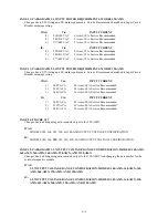
“The
1 PHASE
mode of operation is a one vector output form. … The voltage ranges of the various
transformer output forms are: VR1.5 - 0 to 204 VAC
l-n
(Models 105, 108, 140, 305, 308, 345, 360,
390, and 3120-AMX), VR2.0 - 0 to 273 VAC
l-n
(Models 105, 108, 140, 305, 308, 345, 360, 390, and
3120-AMX), and VR2.5 - 0 to 341 VAC
l-n
(Models 105, 108, 140, 305, 308, 360, 390, and 3120-
AMX).”
IS:
“The
1 PHASE
mode of operation is a one vector output form. … The voltage ranges of the various
transformer output forms are: VR1.5 - 0 to 204 VAC
l-n
(Models 105, 108, 140, 305, 308,
320
, 345,
360, 390, and 3120-AMX), VR2.0 - 0 to 273 VAC
l-n
(Models 105, 108, 140, 305, 308,
320
, 345, 360,
390, and 3120-AMX), and VR2.5 - 0 to 341 VAC
l-n
(Models 105, 108, 140, 305, 308,
320
, 360, 390,
and 3120-AMX).”
WAS:
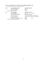
“The
2 PHASE
mode of operation is a two vector output form where the vectors are separated by 180
°
and
equal in amplitude. … The voltage ranges of the various transformer output forms are: VR1.5 - 0 to 408
VAC
l-l
(Models 105, 108, 140, 305, 308, 345, 360, 390, and 3120-AMX), VR2.0 - 0 to 546 VAC
l-l
(Models
105, 108, 140, 305, 308, 345, 360, 390, and 3120-AMX), and VR2.5 - 0 to 600 VAC
l-l
(Models 105, 108,
140, 305, 308, 345, 360, 390, and 3120-AMX). Note that in the case of the Models 305, 308, 330, 345,
360, 390, and 3120-AMX, only two of the three power amplifiers are connected--limiting these systems to
producing only two-thirds of rated output power.
IS:
“The
2 PHASE
mode of operation is a two vector output form where the vectors are separated by 180
°
and
equal in amplitude. … The voltage ranges of the various transformer output forms are: VR1.5 - 0 to 408
VAC
l-l
(Models 105, 108, 140, 305, 308,
320,
345, 360, 390, and 3120-AMX), VR2.0 - 0 to 546 VAC
l-l
(Models 105, 108, 140, 305, 308,
320,
345, 360, 390, and 3120-AMX), and VR2.5 - 0 to 600 VAC
l-l
(Models 105, 108, 140, 305, 308,
320,
345, 360, 390, and 3120-AMX). Note that in the case of the Models
305, 308,
320,
330, 345, 360, 390, and 3120-AMX, only two of the three power amplifiers are connected--
limiting these systems to producing only two-thirds of rated output power.
Summary of Contents for AMX series
Page 1: ......
Page 2: ......
Page 10: ......
Page 11: ......
Page 15: ......
Page 16: ......
Page 19: ...SECTION 2 SPECIFICATIONS 9B THIS PAGE INTENTIONALLY BLANK...
Page 21: ......
Page 22: ......
Page 23: ......
Page 25: ......
Page 26: ......
Page 27: ......
Page 28: ......
Page 29: ......
Page 30: ...SECTION 2 SPECIFICATIONS 19A FIGURE 2 1 2 E2 MODEL 160 AMX OUTPUT DERATING CURVES...
Page 31: ...SECTION 2 SPECIFICATIONS 19B THIS PAGE INTENTIONALLY BLANK...
Page 32: ......
Page 33: ......
Page 34: ......
Page 35: ......
Page 36: ......
Page 37: ......
Page 38: ......
Page 39: ......
Page 40: ......
Page 41: ......
Page 42: ......
Page 45: ...SECTION 2 SPECIFICATIONS 31B THIS PAGE INTENTIONALLY BLANK...
Page 46: ......
Page 47: ......
Page 48: ......
Page 49: ......
Page 50: ...SECTION 2 SPECIFICATIONS 36 FIGURE 2 2 3 OUTLINE DRAWING MODELS 125 140 160 345 360 AMX...
Page 51: ......
Page 56: ......
Page 57: ......
Page 58: ......
Page 59: ......
Page 60: ......
Page 61: ......
Page 62: ......
Page 63: ......
Page 64: ......
Page 65: ......
Page 66: ......
Page 67: ......
Page 70: ......
Page 71: ......
Page 72: ......
Page 73: ......
Page 74: ......
Page 75: ......
Page 76: ......
Page 77: ......
Page 80: ...SECTION 3 INSTALLATION 66 FIGURE 3 3 8 AMX SERIES INPUT WIRING DIAGRAM...
Page 82: ...SECTION 3 INSTALLATION 68 FIGURE 3 4 1 1 SINGLE PHASE OUTPUT CONNECTION...
Page 83: ......
Page 84: ......
Page 85: ......
Page 86: ...SECTION 3 INSTALLATION 72 FIGURE 3 4 2 1 SPLIT PHASE OUTPUT CONNECTION...
Page 87: ......
Page 88: ......
Page 89: ......
Page 90: ......
Page 91: ......
Page 92: ......
Page 93: ......
Page 94: ......
Page 95: ......
Page 96: ......
Page 97: ......
Page 99: ......
Page 100: ......
Page 101: ......
Page 102: ......
Page 104: ......
Page 105: ......
Page 106: ......
Page 107: ......
Page 108: ......
Page 109: ......
Page 110: ......
Page 112: ......
Page 114: ......
Page 116: ......
Page 117: ......
Page 118: ......
Page 120: ......
Page 121: ......
Page 122: ......
Page 124: ...SECTION 7 SERVICE 108B THIS PAGE INTENTIONALLY LEFT BLANK...
Page 125: ......
Page 126: ......
Page 127: ......
Page 128: ......
Page 129: ......
Page 130: ......
Page 131: ......
Page 132: ......
Page 133: ......
Page 134: ......
Page 135: ......
Page 136: ......
Page 137: ......
Page 138: ......
Page 139: ......
Page 140: ......
Page 141: ......
Page 142: ......
Page 143: ......
Page 144: ......
Page 145: ......
Page 146: ......
Page 147: ......
Page 149: ......
Page 150: ......
Page 151: ......
Page 152: ......
Page 159: ......


