background image

37

S-20 AUTO SCRUBBER - FRAME ASSEMBLY, TRACTION

Summary of Contents for S-20

Page 1: ...lly inspect all components to ensure that there is no concealed freight damage If such damage is discovered file a CONCEALED DAMAGE REPORT immediately with the delivering carrier The contents of this...

Page 2: ...losionifmachineisusedinanareawhereflammablevapors liquidsorcombustibledustsarepresent WARNING Donotpickupflammableorreactivematerials WARNING Batteriesemithydrogengas Keepsparksandopenflameaway Keepba...

Page 3: ...edreplacementparts NOTE Allrepairsmustbeperformedbyaqualifiedserviceperson CAUTION Whenservicingthemachine donotmodifythemachinefromitsoriginaldesign NOTE Whentransportingthemachine turnthemachineoff...

Page 4: ...ry compartment beneath the recovery tank To insert batteries 1 Lift the recovery water tank opening it as far as it will go using the side handle 2 The batteries must be lowered into the compartment u...

Page 5: ...also protects the batteries from being fully discharged AGM battery equipped units should not be used after the last yellow LED goes out leaving only red LEDs Using the unit beyond this point can redu...

Page 6: ...has just begun Yellow indicates charge cycle is in the second phase Green indicates charge cycle is complete On board charger 1 On board charger cord wrap 2 Quick release hook 3 The S 20 can be equipp...

Page 7: ...ries that Pacific Floorcare provides Using other battery types not specified for the S 20 by Pacific Floorcare may impair performance of the unit and will affect the life of the batteries To access th...

Page 8: ...l charge while if solid green the batteries are fully charged There is a red fault LED as well In the rare occurence that this LED comes on check the charger op erator manual for troubleshooting guida...

Page 9: ...o match the type of battery chosen in the original machine order Should you choose to change from the original battery type to the other the charger can be changed by re setting the dip switch To re s...

Page 10: ...dded to the S 20 s rear hose fill port located to the left of the control panel There is also a front fill port that is able to accept hose or bucket filling Liquid detergent should be added to the ta...

Page 11: ...20 pad driver 1 2 3 Place your pad driver on a work surface and remove the center lock fitting from the pad driver Remove the pad driver by locating the automatic off switch on the lower control pane...

Page 12: ...ot pedal to lower the scrub deck down onto the pad driver or brush by depressing the pedal while shifting it to the right Once clear of the lower notch lifting your foot will lower the scrub deck Make...

Page 13: ...still requires the attachment of a traditional cleaning pad first This pad acts as a backer pad which compensates for low and high spots in the floor Proper alignment of pad To attach the pad align th...

Page 14: ...n the easy grip knobs and attach the recovery hose Arrows indicate proper hose routing Align the squeegee assembly retention slots with the easy grip knobs then tighten until secure Attach the recover...

Page 15: ...ON OFF The machine is powered on through a key switch on the upper control panel Turn the key to the ON position You will see the battery meter on the left side of the upper control panel light up to...

Page 16: ...ess the lever while shifting it to the right Once clear of the lower notch lifting your foot will lower the scrub deck into the operating position The S 20 has two down pressure settings The disk unit...

Page 17: ...ion flow the brush motor and traction drive if equipped This unique ergonomic design accommodates different operator heights by allowing the user to activate the trigger from any position on the handl...

Page 18: ...r foot on the foot pad and depressing the lever until it clears the lower notch Once clear shift the lever to the left and place it into the lower notch To raise the squeegee lift the squeegee lever h...

Page 19: ...crub head for damage disk models only X Thoroughly clean entire machine X Check linkages and connectors for wear damage X Check all bearings and wheels for noise or loose hardware X Check recovery tan...

Page 20: ...ball float system The drain hose has a press fit cap that is removed for the draining process 1 The hose is also equipped with a restriction collar that can be bent or squeezed to reduce splashing and...

Page 21: ...learly defined or worn halfway through the thickness of the blade then it is time for replacement or to be flipped to another edge The S 20 s squeegee blades have four usable edges Blade exchange is c...

Page 22: ...is completed open the vent caps and look inside the fill wells Add distilled water until the electrolyte level is approximately 1 8 in 3 2 mm below the bottom of the fill well Clean and replace the v...

Page 23: ...r 1 second and then depress position B For the orbital unit simply pull off the pad taking care to follow proper safety precautions as indicated on your chemical product label in regards to coming in...

Page 24: ...rom the machine Reverse the order of the instructions above to install new batteries by orienting and connecting the batteries as shown in the Battery Connection Diagram After installation is complete...

Page 25: ...wear or damage to four isolators in the front and four in the rear of the scrub head The location of the isolators is shown below 1 2 Cross section view of FRONT of orbital scrub head with isolator l...

Page 26: ...n frame 1 NOTE Whentransportingthemachine turnthemachineoff CAUTION Whentransportingthemachine donotliftthemachinewhenbatteriesareinstalled CAUTION Whentransportingthemachine getassistancewhenliftingt...

Page 27: ...ecovery tank orifice After checking for wear wipe the blade or flip it to a new edge 1 1 If still not picking up water then it is likely you have a clog in the recovery hose Start by checking the reco...

Page 28: ...d it will need to be replaced However if the light is on and is blinking then the batteries aren t fully charged and the charge cycle needs to be completed Also check for the fault LED to be lit and i...

Page 29: ...he solution flow adjustment knob is properly positioned then the filter is likely clogged with debris and needs to be cleaned Start by draining the solution tank Unscrew the inline filter located on t...

Page 30: ...ared If the clog is located here clear the clog with your hand or a tool and then drain as normal If the clog is not located at the restriction collar then it is likely in the recovery tank at the dra...

Page 31: ...s Should it be stopping well short of this then it is likely that the recovery hose is not routed properly and has become an obstruction Properly routed loop hose trap placed between knob and recovery...

Page 32: ...ly and check for a clog in the neck of the assembly Recovery hose may be damaged Check for damage Replace if damage found Squeegee assembly height may be out of adjustment Check the squeegee height Se...

Page 33: ...y Contact a service center for testing Vacuum motor will not turn on Squeegee is still in transport storage position Lower squeegee to operating position Vacuum motor relay may be faulty Contact a ser...

Page 34: ...ies Three Traction drive motor tripped Remove overload condition and reset Traction drive motor has short circuited Contact a service center for testing Four Battery lockout has occurred Recharge batt...

Page 35: ...Filter inline 843319 1 1 1 Frame Valve solenoid 859401 1 1 1 Head Motor brush 855201 1 1 Head Guide driver 853803 1 1 Head Guide pad 853804 1 1 Head Plunger spring 857002 1 1 Head Wheel guide 859703...

Page 36: ...Recovery Foam noise vacuum 853306 1 1 1 Recovery Hose squeegee 90 cuff 854102 1 1 1 Solution Hose sight 859202 3 ft 3 ft 3 ft Squeegee Linkage Bearing rod end 902051 1 1 1 Squeegee Linkage Wheel sque...

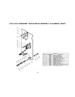
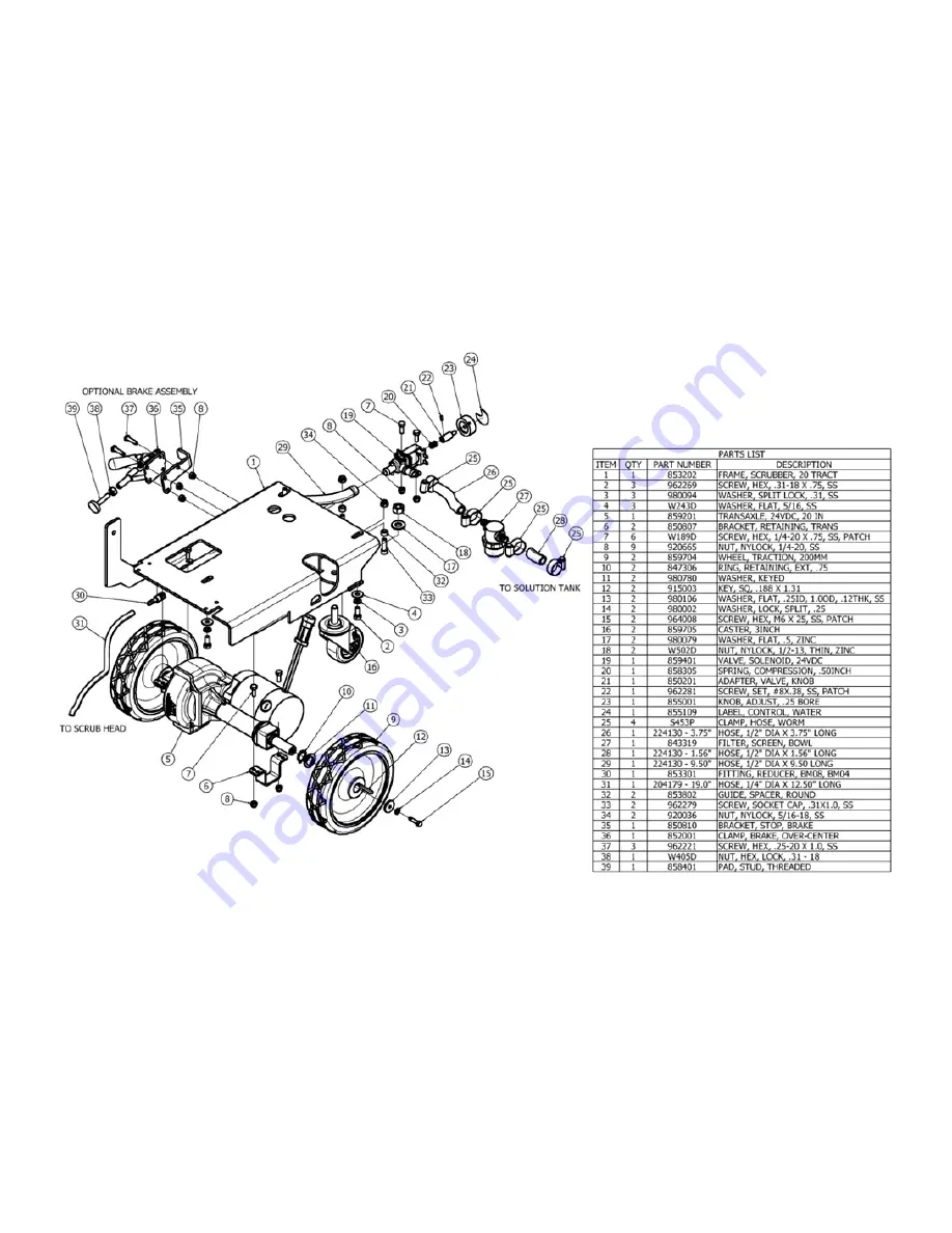
Page 37: ...37 S 20 AUTO SCRUBBER FRAME ASSEMBLY TRACTION...

Page 38: ...38 S 20 AUTO SCRUBBER FRAME ASSEMBLY PAD BRUSH ASSIST...

Page 39: ...39 S 20 AUTO SCRUBBER SOLUTION TANK ASSEMBLY...

Page 40: ...34 S 20 AUTO SCRUBBER BATTERY ASSEMBLY...

Page 41: ...41 S 20 AUTO SCRUBBER RECOVERY TANK ASSEMBLY...

Page 42: ...42 S 20 AUTO SCRUBBER SQUEEGEE ASSEMBLY...

Page 43: ...43 S 20 AUTO SCRUBBER SQUEEGEE LINK ASSEMBLY...

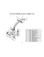
Page 44: ...44 S 20 AUTO SCRUBBER HEAD LIFT ASSEMBLY DISK...

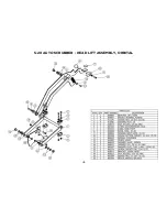
Page 45: ...45 S 20 AUTO SCRUBBER HEAD LIFT ASSEMBLY ORBITAL...

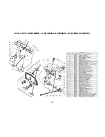
Page 46: ...46 S 20 AUTO SCRUBBER HEAD ASSEMBLY DISK...

Page 47: ...47 S 20 AUTO SCRUBBER HEAD ASSEMBLY ORBITAL...

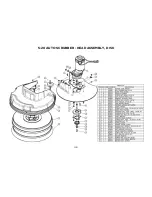
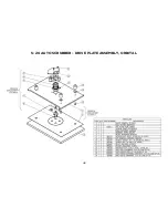
Page 48: ...48 S 20 AUTO SCRUBBER DRIVE PLATE ASSEMBLY ORBITAL...

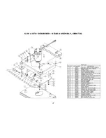
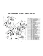
Page 49: ...49 S 20 AUTO SCRUBBER CONTROLS ASSEMBLY TRACTION...

Page 50: ...50 S 20 AUTO SCRUBBER CONTROLS ASSEMBLY PAD BRUSH ASSIST...

Page 51: ...51 S 20 AUTO SCRUBBER ELECTRONICS ASSEMBLY TRACTION...

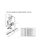
Page 52: ...52 S 20 AUTO SCRUBBER ELECTRONICS ASSEMBLY PAD BRUSH ASSIST...

Page 53: ...53 S 20 AUTO SCRUBBER CHARGER ASSEMBLY ON BOARD...

Page 54: ...S 20 AUTO SCRUBBER WIRING DIAGRAM TRACTION DRIVE DISK...

Page 55: ...S 20 AUTO SCRUBBER WIRING DIAGRAM PAD BRUSH ASSIST DISK...

Page 56: ...S 20 AUTO SCRUBBER WIRING DIAGRAM ORBITAL...

Page 57: ...or for other instructions pertaining to your warranty difficulty 2 Upon compliance with the above warranty procedure all warranted repairs will be completed at no additional charge or cost to the use...

Reviews: