25
MAINTENANCE
END OF SHIFT
Once you’ve completed your daily scrubbing, project work or finish maintenance, proper end of use maintenance can greatly extend the
machine’s life, improve performance, enhance sanitization and lower the machine’s long-term operational costs. There are four key areas we
will review and demonstrate: the recovery tank, squeegee assembly, battery maintenance and charging, ending with pad and brush
maintenance.
RECOVERY TANK
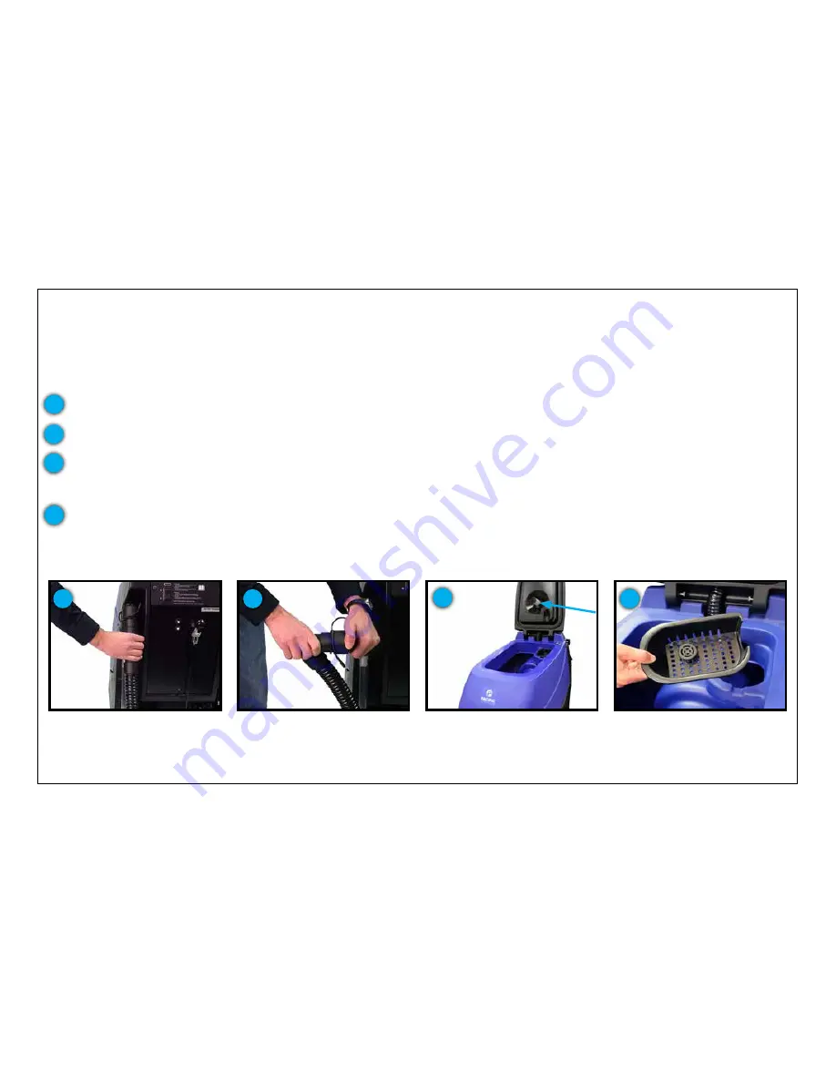
At the end of the job, the recovery tank needs to be emptied and rinsed out. To drain the recovery tank, utilize the recovery tank drain hose
at the rear of the machine.
Recovery tank drain hose
Drain hose has a press-fit cap and
restriction collar
Vacuum mesh filter screen and ball
float system indicated above
Empty debris tray and clean out
The drain hose has a press-fit cap that is removed for the draining process.
1
The hose is also equipped with a restriction collar that can be bent or squeezed to reduce splashing and spraying during the operation.
As the recovery tank drains, lift the recovery tank lid to the fully open position. When almost empty, begin to rinse out the sediment
from the bottom of the tank with a clean water hose. After the tank is thoroughly rinsed and drained, leave the tank lid open to dry. This
is a great time to inspect and clean the vacuum mesh filter screen and ball float system. This can be removed for cleaning by
unscrewing the filter screen and rinsing it with a hose or faucet.
Empty and clean the debris tray after every use. Operating the machine without the debris tray can lead to a clogged outlet hose or
facility drain
The full access tank is designed for periodic deep cleaning and sanitizing. Once thoroughly rinsed, the operator can use a cleaner and
sanitizer with a cloth or sponge to completely sanitize the recovery tank. This reduces the mold and mildew that can form over time.
2
3
4
1
2
3
4
Summary of Contents for S Series
Page 45: ...45 FRAME ASSEMBLY WITH URETHANE WHEELS...
Page 46: ...46 FRAME ASSEMBLY WITH FOAM FILLED WHEELS...
Page 48: ...48 ON BOARD CHEMICAL INJECTION ASSEMBLY OPTIONAL...
Page 49: ...49 BATTERY ASSEMBLY...
Page 50: ...50 RECOVERY TANK ASSEMBLY...
Page 51: ...51 SQUEEGEE ASSEMBLY S 24...
Page 52: ...SQUEEGEE ASSEMBLY S 28 52...
Page 53: ...SQUEEGEE ASSEMBLY S 32 53...
Page 54: ...54 SQUEEGEE LINKAGE ASSEMBLY...
Page 55: ...55 HEAD LIFT ASSEMBLY...
Page 56: ...56 HEAD ASSEMBLY DRAWING 1 OF 2 S 24...
Page 57: ...57 HEAD ASSEMBLY DRAWING 2 OF 2 S 24...
Page 58: ...58 HEAD ASSEMBLY S 28 DISK...
Page 59: ...59 HEAD ASSEMBLY S 32...
Page 60: ...60 HEAD ASSEMBLY LOWER S 28 ORBITAL...
Page 61: ...61 HEAD ASSEMBLY UPPER S 28 ORBITAL...
Page 62: ...62 CONTROLS ASSEMBLY S 24...
Page 63: ...63 CONTROLS ASSEMBLY S 28 S 32 DISK...
Page 64: ...64 CONTROLS ASSEMBLY S 28 ORBITAL...
Page 65: ...65 CONTROLS ASSEMBLY BATTERYSHIELDTM CHEMICAL INJECTION SYSTEM OPTIONAL...
Page 66: ...66 ELECTRONICS ASSEMBLY S 24...
Page 67: ...67 ELECTRONICS ASSEMBLY S 28 S 32 DISK...
Page 68: ...68 ELECTRONICS ASSEMBLY S 28 ORBITAL...
Page 69: ...69 ELECTRONICS ASSEMBLY BATTERYSHIELDTM...
Page 70: ...70 CHARGER ASSEMBLY ON BOARD...
Page 71: ...WIRING DIAGRAM S 24...
Page 72: ...WIRING DIAGRAM S 28 S 32 DISK...
Page 73: ...WIRING DIAGRAM S 28 ORBITAL...
Page 74: ...WIRING DIAGRAM BATTERYSHIELD OPTIONAL 74...
Page 75: ...WIRING DIAGRAM ON BOARD CHEMICAL INJECTION SYSTEM OPTIONAL 75...


