33
TRANSPORTING YOUR UNIT
Your S-Series mid-size scrubber was designed so that it could easily be transported on a route cleaning program.
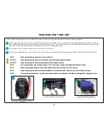
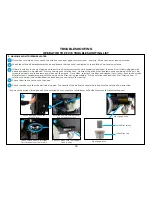
The machine has a tie down holes on each side of the main frame.
It can also be strapped down to a trailer or truck bed using tie down straps inserted between the recovery tank and solution tank
2
3
Tie down locations between
recovery tank and solution tank
3
Tie down location on main frame
2
NOTE:
When transporting the machine, turn the machine off.
CAUTION:
When transporting the machine, do not lift the machine when batteries are installed.
CAUTION:
When transporting the machine, get assistance when lifting the machine.
NOTE:
Use a recommended ramp with a maximum of a 12
°
incline when loading or unloading into/off truck or trailer.
NOTE:
When trasporting the machine, use tie down straps to secure the machine to the truck or trailer
NOTE:
When transporting the machine, put the scrub head in the lowered position. Make sure the unit is off before doing so.
NOTE:
Do not allow the orbital head to rest on a hard surface without a pad attached. This will cause damage to the Mighty-Lok® face.
1
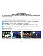
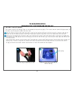
Squeegee assembly in transport
position
1
Easily transport machines in, out or through facilities with the S-Series mid-size scrubber’s unique squeegee hanger feature. Simply
remove the squeegee assembly (see Page 14) while leaving the recovery hose attached, lift the squeegee to a vertical position on the
right side of the machine and place the squeegee tab into the squeegee hanger.
Summary of Contents for S Series
Page 45: ...45 FRAME ASSEMBLY WITH URETHANE WHEELS...
Page 46: ...46 FRAME ASSEMBLY WITH FOAM FILLED WHEELS...
Page 48: ...48 ON BOARD CHEMICAL INJECTION ASSEMBLY OPTIONAL...
Page 49: ...49 BATTERY ASSEMBLY...
Page 50: ...50 RECOVERY TANK ASSEMBLY...
Page 51: ...51 SQUEEGEE ASSEMBLY S 24...
Page 52: ...SQUEEGEE ASSEMBLY S 28 52...
Page 53: ...SQUEEGEE ASSEMBLY S 32 53...
Page 54: ...54 SQUEEGEE LINKAGE ASSEMBLY...
Page 55: ...55 HEAD LIFT ASSEMBLY...
Page 56: ...56 HEAD ASSEMBLY DRAWING 1 OF 2 S 24...
Page 57: ...57 HEAD ASSEMBLY DRAWING 2 OF 2 S 24...
Page 58: ...58 HEAD ASSEMBLY S 28 DISK...
Page 59: ...59 HEAD ASSEMBLY S 32...
Page 60: ...60 HEAD ASSEMBLY LOWER S 28 ORBITAL...
Page 61: ...61 HEAD ASSEMBLY UPPER S 28 ORBITAL...
Page 62: ...62 CONTROLS ASSEMBLY S 24...
Page 63: ...63 CONTROLS ASSEMBLY S 28 S 32 DISK...
Page 64: ...64 CONTROLS ASSEMBLY S 28 ORBITAL...
Page 65: ...65 CONTROLS ASSEMBLY BATTERYSHIELDTM CHEMICAL INJECTION SYSTEM OPTIONAL...
Page 66: ...66 ELECTRONICS ASSEMBLY S 24...
Page 67: ...67 ELECTRONICS ASSEMBLY S 28 S 32 DISK...
Page 68: ...68 ELECTRONICS ASSEMBLY S 28 ORBITAL...
Page 69: ...69 ELECTRONICS ASSEMBLY BATTERYSHIELDTM...
Page 70: ...70 CHARGER ASSEMBLY ON BOARD...
Page 71: ...WIRING DIAGRAM S 24...
Page 72: ...WIRING DIAGRAM S 28 S 32 DISK...
Page 73: ...WIRING DIAGRAM S 28 ORBITAL...
Page 74: ...WIRING DIAGRAM BATTERYSHIELD OPTIONAL 74...
Page 75: ...WIRING DIAGRAM ON BOARD CHEMICAL INJECTION SYSTEM OPTIONAL 75...


