37
TROUBLESHOOTING
OPERATOR TOP FIVE TROUBLESHOOTING LIST
4. RECOVERY TANK NOT DRAINING
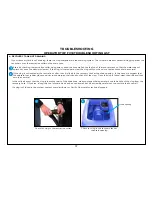
If your recovery tank is not draining, there is a clog somewhere in the draining system. The two main areas of potential clogging are at the
tank drain or at the restriction collar on the drain hose.
Check for clog in the restriction collar
Check for clog in the recovery tank at
the drain opening
Drain opening
1
2
Start by checking the restriction collar being sure to keep the hose well above the top of the recovery tank so that the water doesn’t
splash out once the debris is cleared. If the clog is located here, clear the clog with your hand or a tool and then drain as normal.
If the clog is not located at the restriction collar, then it is likely in the recovery tank at the drain opening. In this case, we suggest that
the operator put rubber gloves on prior to submerging their hand to check for the clog. Once the clog is found, clear the drain and then
empty as normal.
In the unlikely event that the clog is in another part of the drain hose, we encourage utilizing a water hose to back flush the clog from the
recovery hose. Of course, a long thin tool of some kind can be used as well, but be extremely careful not to puncture the hose wall.
If a clog isn’t found in the system, contact your distributor or Pacific Floorcare for technical support.
1
2
Summary of Contents for S Series
Page 45: ...45 FRAME ASSEMBLY WITH URETHANE WHEELS...
Page 46: ...46 FRAME ASSEMBLY WITH FOAM FILLED WHEELS...
Page 48: ...48 ON BOARD CHEMICAL INJECTION ASSEMBLY OPTIONAL...
Page 49: ...49 BATTERY ASSEMBLY...
Page 50: ...50 RECOVERY TANK ASSEMBLY...
Page 51: ...51 SQUEEGEE ASSEMBLY S 24...
Page 52: ...SQUEEGEE ASSEMBLY S 28 52...
Page 53: ...SQUEEGEE ASSEMBLY S 32 53...
Page 54: ...54 SQUEEGEE LINKAGE ASSEMBLY...
Page 55: ...55 HEAD LIFT ASSEMBLY...
Page 56: ...56 HEAD ASSEMBLY DRAWING 1 OF 2 S 24...
Page 57: ...57 HEAD ASSEMBLY DRAWING 2 OF 2 S 24...
Page 58: ...58 HEAD ASSEMBLY S 28 DISK...
Page 59: ...59 HEAD ASSEMBLY S 32...
Page 60: ...60 HEAD ASSEMBLY LOWER S 28 ORBITAL...
Page 61: ...61 HEAD ASSEMBLY UPPER S 28 ORBITAL...
Page 62: ...62 CONTROLS ASSEMBLY S 24...
Page 63: ...63 CONTROLS ASSEMBLY S 28 S 32 DISK...
Page 64: ...64 CONTROLS ASSEMBLY S 28 ORBITAL...
Page 65: ...65 CONTROLS ASSEMBLY BATTERYSHIELDTM CHEMICAL INJECTION SYSTEM OPTIONAL...
Page 66: ...66 ELECTRONICS ASSEMBLY S 24...
Page 67: ...67 ELECTRONICS ASSEMBLY S 28 S 32 DISK...
Page 68: ...68 ELECTRONICS ASSEMBLY S 28 ORBITAL...
Page 69: ...69 ELECTRONICS ASSEMBLY BATTERYSHIELDTM...
Page 70: ...70 CHARGER ASSEMBLY ON BOARD...
Page 71: ...WIRING DIAGRAM S 24...
Page 72: ...WIRING DIAGRAM S 28 S 32 DISK...
Page 73: ...WIRING DIAGRAM S 28 ORBITAL...
Page 74: ...WIRING DIAGRAM BATTERYSHIELD OPTIONAL 74...
Page 75: ...WIRING DIAGRAM ON BOARD CHEMICAL INJECTION SYSTEM OPTIONAL 75...


