3
WARNING! For the safe operation of this machine follow
the instructions given in this booklet and the training given
by your supervisor. Failure to do so can result in personal
injury and/or damage to machine and property!
DO NOT OPERATE MACHINE IN AN EXPLOSIVE
ENVIRONMENT!
NEVER USE THIS MACHINE TO PICK UP VOLATILE
OR EXPLOSIVE MATERIALS!
The model shown in this manual is intended for commercial
use.
DO NOT OPERATE MACHINE IN AN EXPLOSIVE
ENVIRONMENT!
ASSEMBLY & OPERATION
1.
Connect one end of the vacuum hose to the intake port
of the extractor located on the top of the unit and the
other end to the wand.
2.
Connect the one end of the solution hose to the brass
water discharge fitting on the lower front of the extrac-
tor and the other end to the valve connection on the
floor wand.
3.
Fill the solution tank (the rectangular opening located
on the top of the machine that does not have a cover)
with warm or hot water, plus a commercial grade carpet
cleaning chemical. Use dilution recommendations lo-
cated on the chemical bottle. This unit holds 12-gal-
lons of liquid.
NOTE: A low-foaming solution should
be used. If not a defoamer must be used to keep the
foam to a minimum during use to protect your vacuum
motor. Defoamer if used is placed in the recovery tank
prior to operating the unit.
4.
Once you have completed all of the above and your
unit is plugged into a grounded outlet, turn on the pump
switch, which will start to pressurize the unit.
5.
Turn on either one or both of the vacuum switches
depending on the amount of suction desired.
6.
Holding the wand with two hands, activate the solution
by squeezing the lever on the wand (located at the top
of the wand). Spray will start to flow from the jets lo-
cated at the pick up end of the wand.
7.
With one hand squeezing the wand lever, the other hand
should be putting downward pressure on the wand and
dragging the wand backwards across the carpet towards
the operator. This is basically wringing the water out
OPERATING INSTRUCTIONS
of the carpet and pulling dirt embedded in the carpet up
while the suction created by the vacuum motor picks up
the water & dirt and empties it into the recovery tank.
8.
Repeat step #7 without putting more solution down to
extract greater quanities of water from the carpet. Do-
ing this extra times will shorten the drying time required
for your carpet.
9.
After using all of the solution from the solution tank,
you should empty the recovery tank using the dump
valve located at the lower rear of the machine by bring-
ing the unit to a janitor’s sink, commode, etc. and pull-
ing up on the “T” handle on the top of the valve.
10. Once the recovery tank is emptied, lower the “T” handle
and repeat steps 3-9 as needed to clean the remaining
carpet.
11. The cover on the recovery tank must always be in place
while using the extractor. The suction from the unit
during operation holds this in place.
12. During recovery, note that 100% recovery of all liquid
will not be achieved.
DAILY OR REGULAR MAINTENANCE
1.
Rinse solution and recovery tanks out after every use.
Never leave any liquid in the system after use during
storage. Store unit in a warm place. If unit is left in a
freezing environment with liquid left in the system, the
pump and pump housing could crack, requiring replace-
ment of the pump.
2.
Twice a month, flush machine with a solution of white
vinegar (one quart vinegar to two gallons of water) or
anti-browning solution mixed as directed. This will pre-
vent build up of alkaline residue in the machine.
3.
If spray jet on the wand becomes clogged, remove spray
tip, wash thoroughly and blow dry.
PERIODIC MAINTENANCE
1.
Periodically inspect all hoses, electrical cable and con-
nections on the machine. Frayed or cracked hoses
should be replaced to eliminate vacuum or water pres-
sure loss. Check power cable for damage. Repair or
replace damaged cord to prevent fire or electric shock.
Summary of Contents for Triumph 1200
Page 5: ...TRIUMPH 1200 FINALASSEMBLY 4 6 7 8 9 10 11...
Page 7: ...TRIUMPH 1200 RECOVERYTANK 6...
Page 9: ...TRIUMPH 1200 SOLUTIONTANK 8...
Page 11: ...TRIUMPH 1200 BASEASSEMBLY 10...
Page 13: ...TRIUMPH 1200 HOSEASSEMBLY 12...
Page 15: ...TRIUMPH 1200 WANDASSEMBLY 14 1 2 3 4 5 6 7 6 8 9 10 11 12...
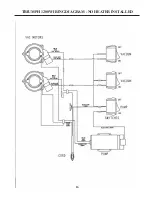
Page 17: ...16 TRIUMPH 1200WIRINGDIAGRAM NO HEATER INSTALLED...
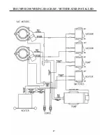
Page 18: ...17 TRIUMPH 1200WIRINGDIAGRAM WITH HEATER INSTALLED...
Page 19: ...NOTES 18...


