


Page 6 of 38
MACHINE PREPARATION
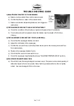
4) SQUEEGEE ASSEMBLY INSTALLATION
The squeegee is assembled to the machine
by lifting the locking latches and sliding the
squeegee assembly onto the 2 posts at the
rear of the squeegee swing arm. Push on the
locking latches down. Lower the squeegee
and install vacuum hose over vacuum outlet
on squeegee assembly. The hose should be
located to the rear of the lifting cable.
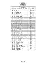
5) ADJUSTING SQUEEGEE HEIGHT
The height from floor to squeegee should be
adjusted based on blade wear. Rotate the
adjusting knobs counter-clockwise to lower
squeegee and clockwise to lift it.
NOTE:
Rotate the right and left adjusting
knobs until the squeegee is positioned parallel
to the floor.
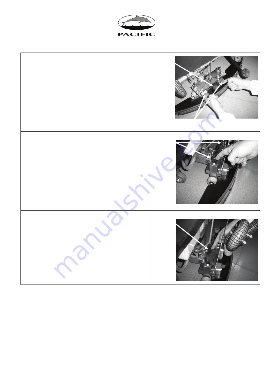
6) ADJUSTING SQUEEGEE INCLINATION
During operation the rear squeegee blade is
most efficient when bent backwards roughly
3/16
ths
to 5/16
ths
of an inch along its entire
length.
To increase the blade bending in the
center of the squeegee, tilt the squeegee body
backward by turning the adjuster knob
counter-clockwise. Conversely, turn the
adjuster knob clockwise to increase the
bending at the outside edges of squeegee
blade.
Locking Latches
Vacuum
Outlet
Height
Adjusting
Knobs
Inclination
Adjusting
Knob
Summary of Contents for Z210
Page 18: ...Page 18 of 38 Brush Deck Assembly Drawing 1...
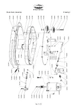
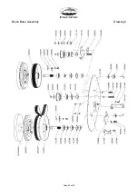
Page 20: ...Page 20 of 38 Brush Base Assembly Drawing 2...
Page 22: ...Page 22 of 38 Main Frame Assembly Drawing 3...
Page 24: ...Page 24 of 38 Squeegee Arm Assembly Drawing 4...
Page 26: ...Page 26 of 38 Squeegee Assembly Drawing 5...
Page 28: ...Page 28 of 38 Solution Tank Assembly Drawing 6...
Page 30: ...Page 30 of 38 Recovery Tank Assembly Drawing 7...
Page 32: ...Page 32 of 38 Vacuum Assembly Drawing 8...
Page 34: ...Page 34 of 38 Switch Box Assembly Drawing 9...
Page 36: ...Page 36 of 38 Electrical Schematic Drawing 10...


