| 12
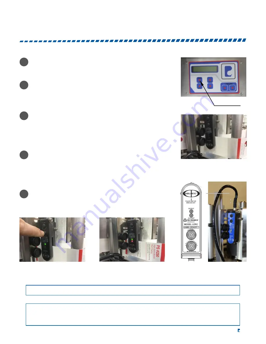
SENSITIVITY ADJUSTING OF LABEL SENSOR
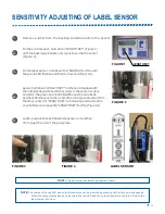
Remove a label from the backing substrate before the sensor.
On the control panel, hold down “LENGTH SET” (Figure 1)
until the backing substrate only is positioned in the sensor
(Figure 2).
On the label sensor, hold down the “NORMAL” button until
the green LED flashes and then turns solid (Figure 3).
Again, hold down “LENGTH SET” on the control panel until
the next label is positioned in the sensor. If the sensor is setup
correctly, the green and red LED will be on when a label is
positioned in the sensor. Also, check the control panel and confirm
that the counter for “LENGTH SET” is increasing and holding the
count after you release the “LENGTH SET” button (Figure 4).
FIGURE 2
Lastly, position the next label to dispense no more than
3mm past the end of the peel plate.
FIGURE 3
FIGURE 4
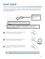
LABEL SENSOR
NOTE:
This sensor cannot detect transparent labels.
NOTE:
The status of the red LED and output transistors can be inverted by pressing both buttons simultaneously.
When the output status has been inverted, the red LED and the output transistors will turn off when the
label comes into view.
FIGURE 1
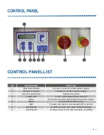
LENGTH SET
1.
4.
3.
2.
5.
Summary of Contents for ELF-50
Page 3: ...MACHINE SPECIFICATIONS ...
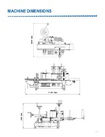
Page 5: ... 5 MACHINE DIMENSIONS 1101 mm 472 mm 1017 mm ...
Page 8: ...GENERALINFORMATION ...
Page 16: ...MACHINEOPERATION ...
Page 24: ...ELECTRONICPANEL ...
Page 25: ...ELECTRONIC DIAGRAM 25 ...
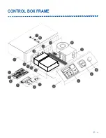
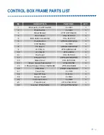
Page 26: ... 26 CONTROL BOX FRAME ...
Page 28: ...APPLICATOR ...
Page 30: ... 30 APPLICATOR MOTOR ASSEMBLY ...
Page 47: ...WRAPSTATION ...
Page 55: ...PRESSUREPLATE ...
Page 58: ...CONVEYOR ...
Page 59: ...CONVEYOR ASSEMBLY 59 ...
Page 64: ...FOOTSTAND ...
Page 65: ...FOOT STAND ASSEMBLY 65 ...
Page 67: ... 67 FOOT STAND ASSEMBLY PART LIST IN FEED TURNTABLE ...
Page 73: ... 73 IN FEED HOLDER ASSEMBLY 5 6 7 8 9 10 11 12 13 14 15 16 17 18 19 20 21 22 23 ...
Page 75: ... 75 OUT FEED TURNTABLE ASSEMBLY OUT FEED TURNTABLE ...


