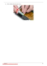


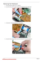


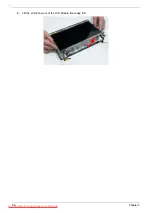

71
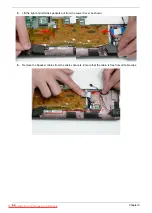
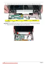
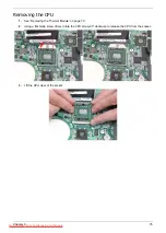
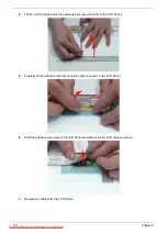
5.
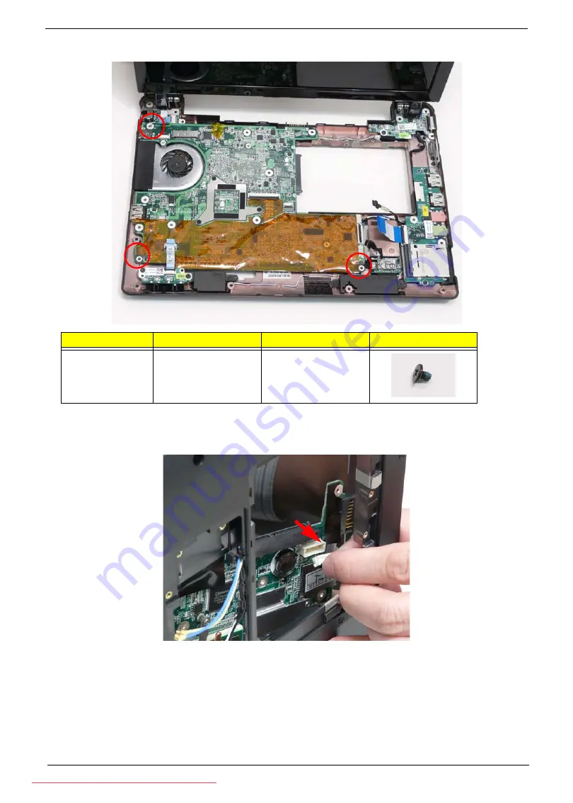
Remove the three screws securing the Mainboard to the Lower Cover as indicated.
6.
Tilt the assembly onto its side so you are able to access the underneath of the mainboard. Lift the
Mainboard right side first to release the I/O ports and separate the board from the Lower Cover.
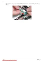
7.
Reach through the HDD bay opening and unplug the VGA cable from the main board.
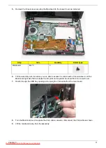
8.
Turn the Mainboard over to expose the VGA cable connector. Disconnect the VGA cable as shown.
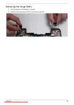
9.
Lift the mainboard away from the assembly.
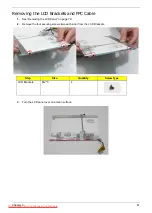
Step
Size
Quantity
Screw Type
Mainboard
M2*3
3
Summary of Contents for DOTMA-111G16i
Page 6: ...VI Downloaded from LpManual com Manuals ...
Page 10: ...X Table of Contents Downloaded from LpManual com Manuals ...
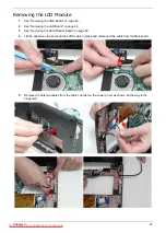
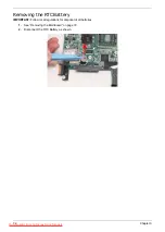
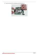
Page 54: ...44 Chapter 3 6 Remove the WLAN Board from the Mainboard Downloaded from LpManual com Manuals ...
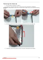
Page 67: ...Chapter 3 57 4 Lift the LED Board from the Lower Cover Downloaded from LpManual com Manuals ...
Page 132: ...122 Chapter 3 Downloaded from LpManual com Manuals ...
Page 154: ...144 Chapter 5 Downloaded from LpManual com Manuals ...
Page 172: ...162 Appendix C Downloaded from LpManual com Manuals ...