11
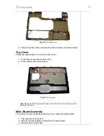
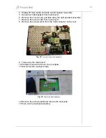
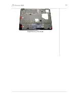
2. Remove the screws (2xK) from the side ODD bracket and remove it.
3. Remove the screws (2xK) from the rear ODD bracket and remove it.
Fig. 19
The screws of the optical disk drive brackets.
Bottom Base Assembly
Disassemble the bottom base assembly as follows:
1. Remove the screws (15xJ, 3xG, 2xB) from the bottom base.
Fig. 20
The bottom base assembly.
2. Remove the screws from the rear (2xB).
Fig. 21
The screws at the bottom base rear.
3. Remove bottom cover from base assembly.
4. Disconnect the subwoofer connector.
5. Remove the screws (2xG) and lift out the subwoofer assembly.
6. Remove the rubber stabilizers (2xM) from the subwoofer assembly.
7. Remove the screw (1xB) from the modem connector board.


