12
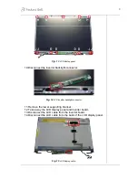
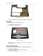
Fig. 22
The bottom cover.
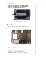
8. Disconnect the cable connector from the modem connector board.
Top Cover
Follow the steps below to remove the top cover:
1. First remove the screws (2xA, 2xL).
2. Then remove the screws (4xJ).
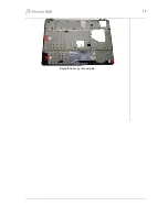
Fig. 23
The top cover.
Note:
Make sure that during re-assembly the clips of the top cover lock into place before
fastening the screws.
Main Board Assembly
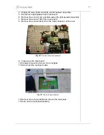
To remove the main board from the top cover, follow the steps below:
1. Flip the top cover around.
2. Disconnect left speaker connector from main board.
3. Remove the screw (1xN).


