Chapter 3
125
9.
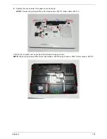
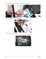
Replace the nine screws in the upper cover as shown.
NOTE:
The securing screws differ in size: Red callout—M2.5*5, Blue callout—M2.5*3.
10.
Turn the computer over and replace the thirteen screws as shown.
NOTE:
The securing screws differ in size: Red callout—M2.5*8, Green callout—M2.5*5, Blue callout—M2.5*3.
Summary of Contents for EasyNote LJ75
Page 6: ...VI ...
Page 10: ...X Table of Contents Online Support Information 207 Index 209 ...
Page 15: ...Chapter 1 5 System Block Diagram ...
Page 58: ...48 Chapter 2 ...
Page 71: ...Chapter 3 61 5 Remove the HDD from the carrier ...
Page 85: ...Chapter 3 75 11 Carefully remove the LCD module from the chassis ...
Page 94: ...84 Chapter 3 5 Lift the entire Speaker assembly clear of the Upper Cover ...
Page 148: ...138 Chapter 3 ...
Page 178: ...168 Chapter 4 ...
Page 186: ...176 Chapter 5 ...
Page 199: ...Chapter 6 189 ...
Page 216: ...206 Appendix B ...
Page 218: ...208 Appendix C ...
Page 222: ...212 ...

