background image

Packard Bell EasyNote S Disassembly Manual

5

Fig. 3

Sliding out the hard disk drive.

Removing the Memory Module

There are two SO-DIMM slots, of which one is easily accessible (for end-users) and the other one
requires more disassembly.

SO-DIMM Slot 1

1.  Remove the screw securing the cover on the bottom of the casing.

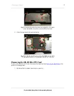
Fig. 4

 Removing the cover screw.

2.  Remove the cover.
3.  Push plastic clips aside.
4.  Take out the SO-DIMM memory module.

Fig. 5

 Taking out the memory module.

Summary of Contents for EasyNote S

Page 1: ...Packard Bell EasyNote S Disassembly Manual ...

Page 2: ...Removing the Optical Disk Drive 6 Removing the Button Panel 6 Removing the Keyboard 7 Removing the Heat Shield 7 Removing the WLAN Mini PCI Card 8 Removing the CPU 9 Removing the VGA Heat Sink 10 Removing the Main Board 10 Removing the Modem 12 Removing the LCD Switch 13 Removing the Subwoofer 13 Removing the Speakers 14 Removing the Glide Pad 15 Removing the Microphone 15 Removing the LCD Assembl...

Page 3: ... board Improper repairs can create a safety hazard Any indication of component replacement or printed wiring board modifications may void any warranty or exchange allowances Disassembly Instructions When disassembling the system unit follow these general rules n Turn off the power and disconnect all cables and peripherals n Label all removed connectors Note where the connector goes and in what pos...

Page 4: ...til it is un installed in the computer Power Supply Unit Under no circumstances should you attempt to disassemble the power supply The power supply contains no user serviceable parts Inside the power supply are hazardous voltages that can cause serious personal injury Always return a defective power supply to your dealer WARNING Ensure that the computer is disconnected from its power source and fr...

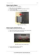
Page 5: ... down 4 Unlock the battery compartment and slide it out of its place Fig 1 Releasing the battery Removing the Hard Disk Drive To remove the hard disk drive then perform the following steps 1 Remove the 2 screws securing the hard disk drive cover on the front side 2 Remove the 2 silver coloured screws underneath Fig 2 Removing the 2 silver coloured screws 3 Pull out the Mylar folded inside the driv...

Page 6: ...MM slots of which one is easily accessible for end users and the other one requires more disassembly SO DIMM Slot 1 1 Remove the screw securing the cover on the bottom of the casing Fig 4 Removing the cover screw 2 Remove the cover 3 Push plastic clips aside 4 Take out the SO DIMM memory module Fig 5 Taking out the memory module ...

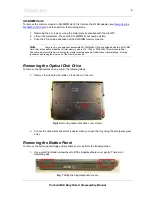
Page 7: ... memory size is 512 1024 or 2048 MB This will enable Dual Channel memory architecture allowing far greater memory speeds Under these circumstances it is not recommended to upgrade just one of the memory modules Removing the Optical Disk Drive To remove the optical disk drive perform the following steps 1 Remove the indicated 2 screws on the bottom of the unit Fig 6 Removing optical disk drive cove...

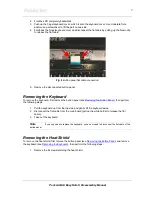
Page 8: ... the keyboard first remove the button panel see Removing the Button Panel then perform the following steps 1 Pull the keyboard up from the top side and gently lift the keyboard away 2 Disconnect the flat cable from the main board pull up the white holder to release the flat cable 3 Take out the keyboard Note If you only need to replace the keyboard you do not need to disconnect the flat cable of t...

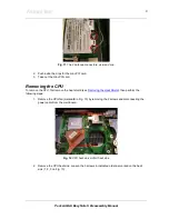
Page 9: ...2 Lift out the heat shield it should look like this Fig 10 A WLAN mini PCI card and 2nd SO DIMM slot B CPU C keyboard connector D glide pad connector E CPU fan Removing the WLAN Mini PCI Card To remove the WLAN mini PCI card first remove the heat shield see Removing the Heat Shield then perform the following steps 1 Disconnect the 2 antenna connectors MAIN and AUX ...

Page 10: ...e CPU To remove the CPU first remove the heat shield see Removing the Heat Shield then perform the following steps 1 Remove the CPU fan marked E in Fig 10 by removing the 2 screws and disconnecting the power cable from the main board Fig 12 CPU heat sink VGA heat sink 2 Remove the CPU heat sink Loosen the 3 screws in indicated order as marked on the heat sink 1 2 3 on Fig 13 ...

Page 11: ...first remove the battery see Removing the Battery remove the hard disk drive see Removing the Hard Disk Drive remove the available memory modules see Removing the Memory Module remove the optical disk drive see Removing the Optical Disk Drive remove the button panel see Removing the Button Panel remove the keyboard see Removing the Keyboard remove the heat shield see Removing the Heat Shield remov...

Page 12: ...ews in the top 4 Flip over the base unit and remove the 11 screws from the bottom of the base Fig 15 10 Large screws A and 1 short screw B 5 Disconnect the flat cable of the glide pad and disconnect the microphone cable Fig 16 Glide pad flat cable and the microphone cable ...

Page 13: ... board Next to the holes of the hex bolts you should see a symbol like an ellipse with a square across Fig 17 Symbol on main board indicating hex bolts 13 Remove the 4 screws on the main board There is an encircled symbol near their holes 14 Slide out the main board Note You have to pull the backside forward quite extensively to release the VGA port Note You can pull the left side of the casing ou...

Page 14: ...t remove the main board see up to step 6 in Removing the Main Board then perform the following steps 1 Disconnect the cable from the main board Fig 19 LCD switch cable connector 2 Remove the screw from the LCD switch and remove the LCD switch Fig 20 Removing the LCD switch screw Removing the Subwoofer To remove the subwoofer first remove the main board see up to step 6 in Removing the Main Board t...

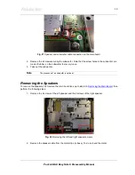
Page 15: ... very loose 3 Take out the subwoofer Note The presence of a subwoofer is optional Removing the Speakers To remove the speakers first remove the main board see up to step 6 in Removing the Main Board then perform the following steps 1 Remove the 2 screws of the left speaker and the 2 screws of the right speaker Fig 22 Removing the left and right speaker screws 2 Remove the speaker cable from the me...

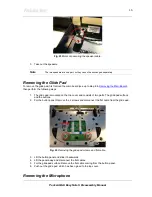
Page 16: ...lowing steps 1 The glide pad is mounted on the top cover and consists of two parts The glide pad surface and the buttons 2 For the button panel Remove the 2 screws and disconnect the flat cable from the glide pad Fig 24 Removing the glide pad screws and flat cable 3 Lift the button panel and slide it backwards 4 Lift the panel away and disconnect the flat cables 5 For the glide pad surface Remove ...

Page 17: ...g the top cover cable 3 Remove the microphone Removing the LCD Assembly To remove the LCD assembly first remove the heat shield see Removing the Heat Shield then perform the following steps 1 Disconnect the LCD cable from the main board Fig 26 LCD cable connection on the main board 2 Remove the 2 screws on the back of the system 3 Remove the 2 screws in the bottom base directly under the screws yo...

Page 18: ... and 2 at the bottom Fig 27 Location of rubber stoppers on the LCD assembly 2 Remove the 6 screws underneath the stoppers 3 Remove the LCD bezel The bezel has been clicked into place and you need to pull hard to loosen it 4 Disconnect the cables from the inverter board Fig 28 Power cable connected to the inverter board ...

Page 19: ...he LCD panel 7 Remove the metal brackets on each side 4 screws per side 8 LCD data cable Press the metal holder on each side and pull the cable loose from the connector on the LCD panel Fig 31 Disconnecting the LCD data cable Removing the Inverter Board To remove the inverter board first remove the LCD panel see up to step 4 in Removing the LCD Panel then perform the following steps 1 Remove the s...

Page 20: ...enna first remove the LCD panel see up to step 6 in Removing the LCD Panel then perform the following steps 1 Remove the metal brackets on the top on each side of the LCD back cover Fig 33 Metal brackets on LCD back cover 2 Release the WiFi antenna and remove it from the back cover Reassembly Notes To clip the keyboard in place you have to insert the keyboard hinges cover into the metal clips moun...

Page 21: ...G PERFORMANCE OR USE OF THIS MATERIAL Copyright 2005 NEC Computers International B V All rights reserved Packard Bell is a trademark of NEC Computers International B V The names of actual companies and products mentioned herein may be trademarks and or registered trademarks of their respective owners The software described in this guide is furnished under a license agreement or nondisclosure agree...

Reviews: