Packard Bell EasyNote S Disassembly Manual
6
SO-DIMM Slot 2
To remove the memory module in SO-DIMM slot 2, first remove the WLAN adapter (see
Removing the
WLAN Mini-PCI Card
), and then perform the following steps:
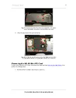
1. Removing the 3 screws securing the metal plate located beneath the mini-PCI.
2. Lift out the metal plate; The second SO-DIMM slot will now be visible.
3. Push the 2 clips aside and take out the SO-DIMM memory module.
Note
There is only one end-user accessible SO-DIMM slot! If the unit shipped with two SO-DIMM
slots, they will usually be identical (if total memory size is 512, 1024 or 2048 MB). This will enable Dual
Channel memory architecture, allowing far greater memory speeds. Under these circumstances, it is
not
recommended to upgrade just one of the memory modules.
Removing the Optical Disk Drive
To remove the optical disk drive, perform the following steps:
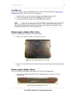
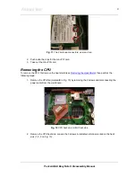
1. Remove the indicated 2 screws on the bottom of the unit.
Fig. 6
Removing optical disk drive cover screws.
2. Pull out the optical disk drive (this is easier when you open the tray using the emergency eject
hole).
Removing the Button Panel
To remove the button panel (hinge and keyboard cover), perform the following steps:
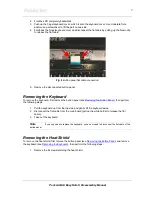
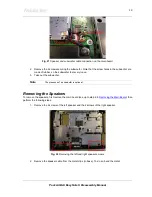
1. Use a small flat-bladed screwdriver to lift the hinge/keyboard cover gently; There are 2
indicated gaps.
Fig. 7
Lifting the hinge/keyboard covers.


