Packard Bell EasyNote S Disassembly Manual
8
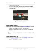
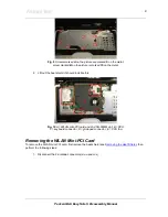
Fig. 9
Screws marked
A
on the picture are marked
5
on the metal;
screw marked
B
on the picture is marked
15
on the metal.
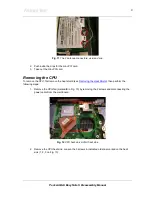
2. Lift out the heat shield; it should look like this:
Fig. 10
A = WLAN mini-PCI card and 2nd SO-DIMM slot; B = CPU;
C = keyboard connector; D = glide pad connector; E = CPU fan.
Removing the WLAN Mini-PCI Card
To remove the WLAN mini-PCI card, first remove the heat shield (see
Removing the Heat Shield
), then
perform the following steps:
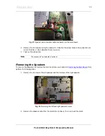
1. Disconnect the 2 antenna connectors (
MAIN
and
AUX
)


