140
Chapter 4
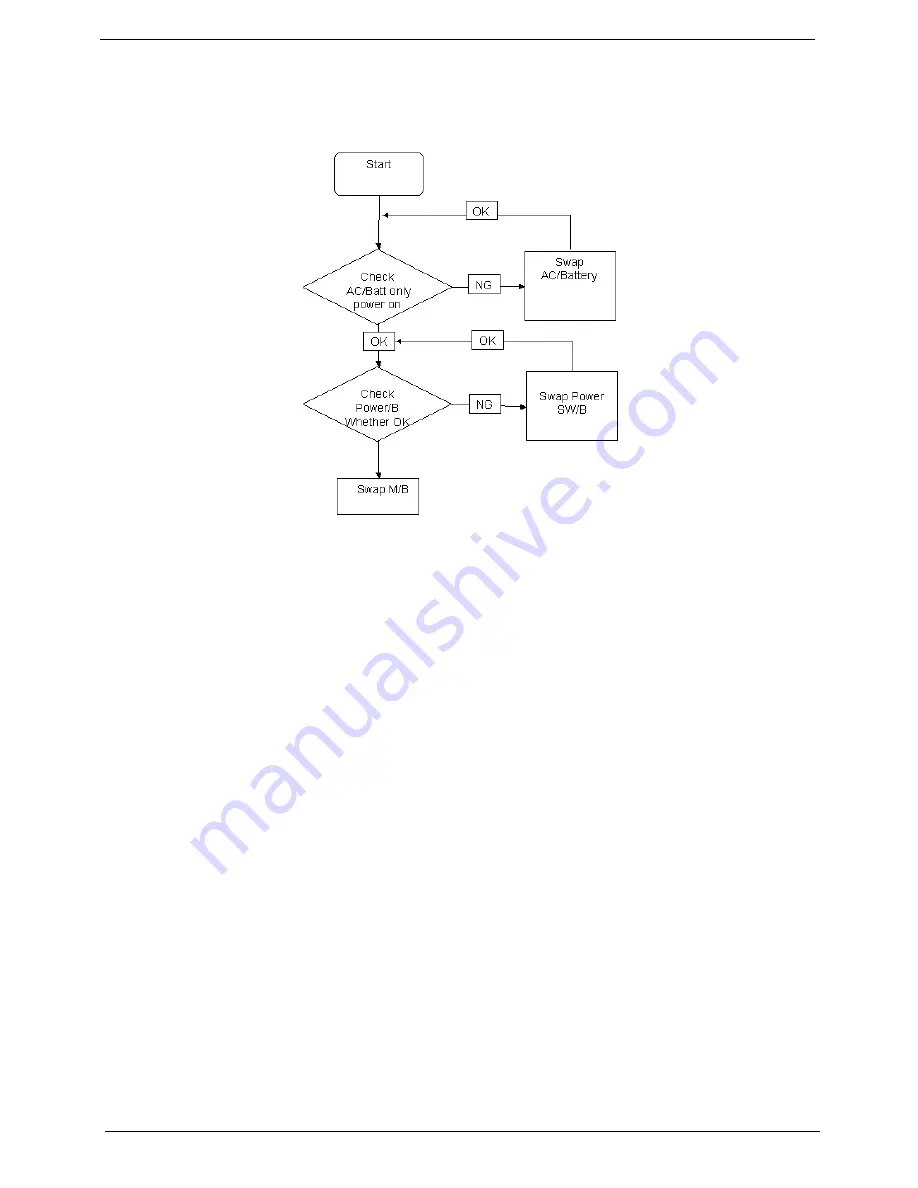
Power On Issue
If the system doesn’t power on, perform the following actions one at a time to correct the problem. Do not
replace a non-defective FRUs:
Computer Shutsdown Intermittently
If the system powers off at intervals, perform the following actions one at a time to correct the problem.
1.
Check the power cable is properly connected to the computer and the electrical outlet.
2.
Remove any extension cables between the computer and the outlet.
3.
Remove any surge protectors between the computer and the electrical outlet. Plug the computer directly
into a known good electrical outlet.
4.
Disconnect the power and open the casing to check the Thermal Unit (see “Thermal Unit Failure” on page
150) and fan airways are free of obstructions.
5.
Remove all external and non-essential hardware connected to the computer that are not necessary to
boot the computer to the failure point.
6.
Remove any recently installed software.
7.
If the Issue is still not resolved, see “Online Support Information” on page 195.
Summary of Contents for ENTK36 Series
Page 6: ...VI ...
Page 10: ...X Table of Contents ...
Page 66: ...56 Chapter 3 4 Detach the WLAN module from the WLAN socket ...
Page 76: ...66 Chapter 3 5 Lift the speaker module clear of the device ...
Page 87: ...Chapter 3 77 10 Disconnect the Bluetooth cable from mainboard ...
Page 92: ...82 Chapter 3 8 Remove the LCD assembly from the lower cover ...
Page 103: ...Chapter 3 93 5 Lift the microphone set clear of the panel ...
Page 114: ...104 Chapter 3 4 Replace the adhesive tape securing the inverter board cable to the LCD cover ...
Page 120: ...110 Chapter 3 7 Replace the adhesive tape to secure the antennas to the lower cover ...
Page 123: ...Chapter 3 113 5 Connect the fan cable ...
Page 130: ...120 Chapter 3 4 Connect the USB cable to the mainboard and lock the connector ...
Page 134: ...124 Chapter 3 Replacing the Upper Cover 1 Place the upper cover on the lower cover as shown ...
Page 136: ...126 Chapter 3 4 Connect the speaker cable B 5 Connect and lock the touchpad FFC C ...
Page 138: ...128 Chapter 3 Replacing the RTC Battery 1 Place the RTC battery into the mainboard connector ...
Page 140: ...130 Chapter 3 4 Slide the HDD module in the direction of the arrow to connect the interface ...
Page 198: ...Appendix A 188 ...
Page 206: ...196 Appendix C ...
Page 210: ...200 ...


