14
Chapter 1
Hardware Specifications and Configurations
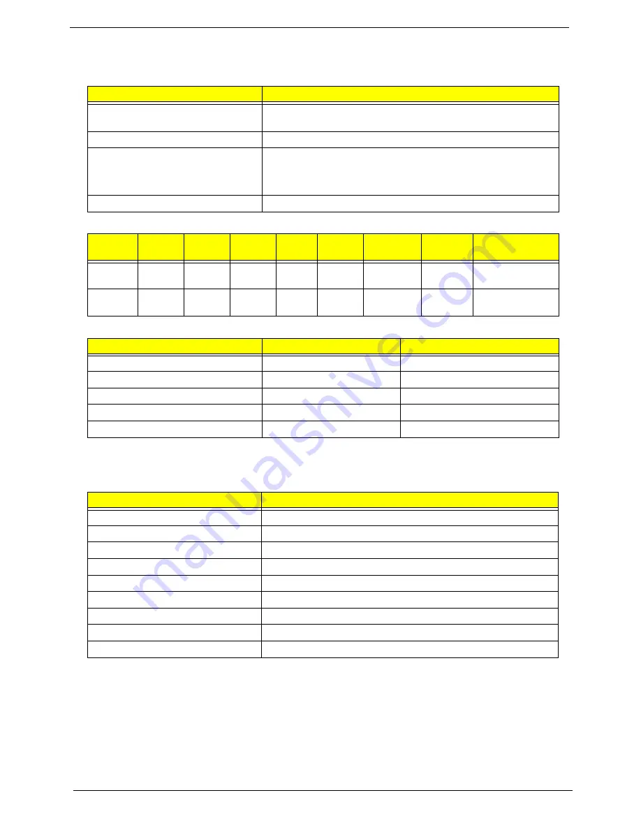
Processor
Processor Specifications
CPU Fan True Value Table
•
Throttling 50%: On= 95C; OFF=80C
•
OS shut down at 100C; H/W shut down at 90C
System Memory
Item
Specification
CPU type
Intel® Pentium® and Intel® Celeron® mobile processors based
on the 45-nm process
CPU package
Micro- FCPGA package
Core Logic
•
Intel Montevina chipset
•
ICH9M Intel 82801GBM
•
On die 512-kB, 8-way L2 cache
Chipset
•
Intel® GL40 Express Chipset
Item
CPU
Speed
Cores
Bus
Speed
Mfg
Tech
Cache
Size
Package
Core
Voltage
Acer PN
CM900
2.2G
2
800M
Hz
45nm
1M
Micro-
FCPGA
1.0V -
1.2V
KC.N0001.900
T3500
21.G
2
800M
Hz
45nm
1M
Micro-
FCPGA
0.8V-
1.25V
KC.35001.CMT
CPU Temperature
Fan Speed (RPM)
SPL Spec (dBA)
50 2400
28
55
2500
31
60
2700
34
65
3000
37
85
3400
40
Item
Specification
Memory controller
Built in (Intel® GL40 Express Chipset)
Memory size
512MB,1GB,2GB DDR3 RAM
DIMM socket number
2
Supports memory size per socket
2 GB
Supports maximum memory size
4 GB
Supports DIMM type
DDR III 667/800Mhz SDRAM memory interface design
Supports DIMM Speed
667/800Mhz SDRAM
Support DIMM voltage
1.5V
Supports DIMM package
DDRIII SDRAM 204pin Unbuffered SODIMM based
Summary of Contents for ENTK36 Series
Page 6: ...VI ...
Page 10: ...X Table of Contents ...
Page 66: ...56 Chapter 3 4 Detach the WLAN module from the WLAN socket ...
Page 76: ...66 Chapter 3 5 Lift the speaker module clear of the device ...
Page 87: ...Chapter 3 77 10 Disconnect the Bluetooth cable from mainboard ...
Page 92: ...82 Chapter 3 8 Remove the LCD assembly from the lower cover ...
Page 103: ...Chapter 3 93 5 Lift the microphone set clear of the panel ...
Page 114: ...104 Chapter 3 4 Replace the adhesive tape securing the inverter board cable to the LCD cover ...
Page 120: ...110 Chapter 3 7 Replace the adhesive tape to secure the antennas to the lower cover ...
Page 123: ...Chapter 3 113 5 Connect the fan cable ...
Page 130: ...120 Chapter 3 4 Connect the USB cable to the mainboard and lock the connector ...
Page 134: ...124 Chapter 3 Replacing the Upper Cover 1 Place the upper cover on the lower cover as shown ...
Page 136: ...126 Chapter 3 4 Connect the speaker cable B 5 Connect and lock the touchpad FFC C ...
Page 138: ...128 Chapter 3 Replacing the RTC Battery 1 Place the RTC battery into the mainboard connector ...
Page 140: ...130 Chapter 3 4 Slide the HDD module in the direction of the arrow to connect the interface ...
Page 198: ...Appendix A 188 ...
Page 206: ...196 Appendix C ...
Page 210: ...200 ...


