background image

Jupiter Disassembly Manual version 1.0

--------------------------------------------------------------------------------------------------

-------------------------------------------------------------------------------------------------- [

Page 2 of 11 ]

Product Support Consumer for NEC Computers International B.V. © 2004

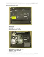
Disassembly Instructions

1. Remove battery

2. Remove HDD cover (1 x screw A)

3. Remove HDD

4. Remove USB cover (1 x screw A)

5. Remove mobo cover (6 x screw A)

6. Remove memory from memory slots (2 x)

7. Remove WiFi MiniPCI card from slot

8. Disconnect antennas

9. Remove screws (2 x screw A) on modem

Summary of Contents for JUPITER

Page 1: ...puters International B V 2004 JUPITER Disassembly Manual Version Modifications Author Date 0 1 Typed text version based on disassembly notes Juan M Calviño Alonso 26 11 04 0 2 Draft version photos D Egberts 26 11 04 1 0 Added password clear and jumpers dipswitch section D Egberts 29 11 04 ...

Page 2: ...rnational B V 2004 Disassembly Instructions 1 Remove battery 2 Remove HDD cover 1 x screw A 3 Remove HDD 4 Remove USB cover 1 x screw A 5 Remove mobo cover 6 x screw A 6 Remove memory from memory slots 2 x 7 Remove WiFi MiniPCI card from slot 8 Disconnect antennas 9 Remove screws 2 x screw A on modem ...

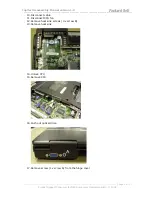
Page 3: ...Support Consumer for NEC Computers International B V 2004 10 Disconnect cable 11 Disconnect CPU fan 12 Remove heat sink screws 3 x screw B 13 Remove heat sink 14 Unlock CPU 15 Remove CPU 16 Push out optical drive 17 Remove screw 1 x screw A from the hinge cover ...

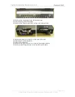
Page 4: ...eyboard locks lift keyboard up 19 Disconnect keyboard flat cable 20 Push up the hinge covers back and up and remove them 21 Remove screws 2 x screw F on the rear of the unit 22 Disconnect 2 LCD connectors 23 Open LCD completely 24 Remove left hinge screws 2 x screw G wireless antenna 25 Remove right hinge screws 2 x screw G earth cable ...

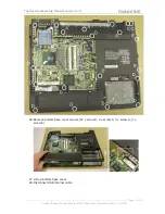
Page 5: ...ion 1 0 Page 5 of 11 Product Support Consumer for NEC Computers International B V 2004 26 Remove bottom base cover screws 12 x screw D 2 x screw C 3 x screw A 3 x screw E 27 Lift up bottom base cover 28 Disconnect USB internal cable ...

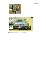
Page 6: ...sion 1 0 Page 6 of 11 Product Support Consumer for NEC Computers International B V 2004 29 Remove screw 1 x screw A from USB HUB board 30 Remove USB HUB board cable from bottom base assy 31 Remove hex bolt 2 x screw H from VGA port ...

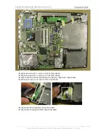
Page 7: ...nal B V 2004 32 Remove hex bolt 1 x screw J from main board 33 Remove hex bolt 1 x screw L from main board 34 Disconnect the modem LAN board connector cable from main board 35 Remove screw 1 x screw F from main board 36 Disconnect the hard disk connector board 37 Disconnect touchpad button board flat cable ...

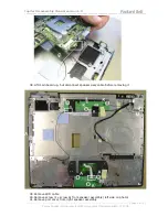
Page 8: ...rt Consumer for NEC Computers International B V 2004 38 Lift main board up but disconnect speaker assy cable before removing it 39 Remove WiFi cable 40 Remove screw 1 x screw A from speaker assembly left side on photo 41 Remove port cover from right speaker assembly ...

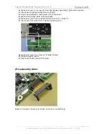
Page 9: ...ouchpad cable from touchpad 44 Push out touchpad to disconnect it from top cover 45 Remove touchpad cable from touchpad 46 Remove screws from touchpad button board 3 x screw A 47 Disconnect flat cable from touchpad button board 48 Remove screws 3 x screw K of button board 49 Remove button board 50 Disconnect button board flat cable Re assembly Notes Battery Connector Cover put it back on when re a...

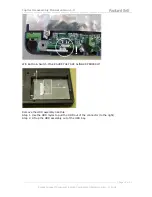
Page 10: ...rt Consumer for NEC Computers International B V 2004 Wifi Button Switch MAKE SURE THEY ARE ALINGED PROPERLY Remove the HDD assembly like this Step 1 Use the HDD mylar to pull the HDD out of the connector to the right Step 2 Lift up the HDD assembly out of the HDD bay ...

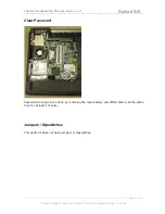
Page 11: ...t Support Consumer for NEC Computers International B V 2004 Clear Password Password clearing can be done by removing the main battery and CMOS battery at the same time for at least 1 minute Jumpers Dipswitches This platform does not have jumpers or dipswitches ...

Reviews: