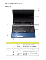
Chapter 1
3
•
802.11b/g/n Wi-Fi CERTIFIED™
•
802.11b/g Wi-Fi CERTIFIED™
•
WPAN:
•
Bluetooth® 2.1
•
LAN:
•
Gigabit Ethernet, Wake-on-LAN ready
Privacy control
•
BIOS user, supervisor, HDD passwords
•
Kensington lock slot
Power subsystem
•
ACPI 3.0 CPU power management standard: supports Standby and Hibernation power-saving
modes
•
3-pin 90 W AC adapter*:
•
133 (W) x 59 (D) x 31 (H) mm (5.23 x 2.32 x 1.22 inches)
•
390 g (0.86 lbs.) with 180 cm DC cable
•
3-pin 65 W AC adapter*:
•
108 (W) x 46 (D) x 29.5 (H) mm (4.25 x 1.81 x 1.16 inches)
•
225 g (0.49 lbs.) with 180 cm DC cable
•
4400 mAh 6-cell Li-ion standard battery pack
•
Estimated battery life: Up to 4 hours, 30 minutes with integrated graphics; up to 3 hours, 20
minutes14 with discrete graphics.
•
ENERGY STAR®
Special keys and controls
•
99-/100-/103-key keyboard
•
Multi-gesture touchpad, supporting two-finger scroll, pinch, rotate, flip
•
Nine function keys, four cursor keys, Windows® key, international language support
I/O interface
•
Multi-in-1 card reader
•
Three USB 2.0 ports
•
HDMI™ port with HDCP support
•
External display (VGA) port
•
Headphone/speaker/line-out jacks
•
Microphone-in jack
•
Ethernet (RJ-45) port
•
DC-in jack for AC adapter
Software
•
Packard Bell Accessory Store (Canada, France, Germany, Italy, Mexico, Spain UK, US only)
Summary of Contents for TM86 Series
Page 6: ...VI ...
Page 10: ...X Table of Contents ...
Page 15: ...Chapter 1 5 System Block Diagram ...
Page 62: ...52 Chapter 3 4 Remove one 1 screw from the 3G module 5 Lift the 3G card from the slot ...
Page 73: ...Chapter 3 63 3 Disconnect the following four 4 cables from the Mainboard A B C D ...
Page 78: ...68 Chapter 3 5 Lift the Right Speaker Module clear of the upper cover ...
Page 83: ...Chapter 3 73 5 Lift the card reader board clear of the device ...
Page 85: ...Chapter 3 75 5 Lift the USB board clear of the device ...
Page 92: ...82 Chapter 3 5 Carefully lift the Thermal Module clear of the Mainboard ...
Page 101: ...Chapter 3 91 5 Turn the board over and disconnect the cable ...
Page 103: ...Chapter 3 93 4 Lift the LCD Panel clear of the module ...
Page 105: ...Chapter 3 95 5 Disconnect the LVDS cable from the panel ...
Page 107: ...Chapter 3 97 5 Lift the microphone set clear of the panel ...
Page 114: ...104 Chapter 3 4 Replace six 6 securing screws three on each side of the LCD Panel brackets ...
Page 126: ...116 Chapter 3 6 Connect the LVDS cable and lock the connector 7 Connect the microphone cable ...
Page 131: ...Chapter 3 121 4 Replace the FFC and press down as indicated to secure it to the Upper Cover ...
Page 187: ...Chapter 6 177 ...
Page 188: ...Appendix A 178 Model Definition and Configuration Appendix A ...
Page 212: ...202 Appendix C ...
Page 216: ...206 ...


