Chapter 1
7
NOTE:
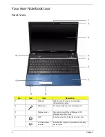
1
The front panel indicators are visible even when the computer cover is closed.
Closed Front View
5
Power button
Turns the computer on and off.
6
Keyboard
For entering data into your computer.
7
Palmrest
Comfortable support area for your hands when
you use the computer.
8
Click buttons (left
and right)
The left and right buttons function like the left
and right mouse buttons.
9
Power
1
Indicates the computer’s power status.
Battery
1
Indicates the computer’s battery status.
1.
Charging: The light shows amber when the
battery is charging.
2.
Fully charged: The light shows blue when in
AC mode.
10
TouchPad
Touch-sensitive pointing device which functions
like a computer mouse.
11
Speakers
Left and right speakers deliver stereo audio
output.
No.
Icon
Item
Description
1
Multi-in-1 card
reader
Accepts Secure Digital (SD), MultiMediaCard
(MMC), Memory Stick (MS), Memory Stick
PRO (MS PRO), xDPicture Card (xD).
NOTE:
Push to remove/install the card.
Only one card can operate at any
given time.
No.
Icon
Item
Description
1
Summary of Contents for TM86 Series
Page 6: ...VI ...
Page 10: ...X Table of Contents ...
Page 15: ...Chapter 1 5 System Block Diagram ...
Page 62: ...52 Chapter 3 4 Remove one 1 screw from the 3G module 5 Lift the 3G card from the slot ...
Page 73: ...Chapter 3 63 3 Disconnect the following four 4 cables from the Mainboard A B C D ...
Page 78: ...68 Chapter 3 5 Lift the Right Speaker Module clear of the upper cover ...
Page 83: ...Chapter 3 73 5 Lift the card reader board clear of the device ...
Page 85: ...Chapter 3 75 5 Lift the USB board clear of the device ...
Page 92: ...82 Chapter 3 5 Carefully lift the Thermal Module clear of the Mainboard ...
Page 101: ...Chapter 3 91 5 Turn the board over and disconnect the cable ...
Page 103: ...Chapter 3 93 4 Lift the LCD Panel clear of the module ...
Page 105: ...Chapter 3 95 5 Disconnect the LVDS cable from the panel ...
Page 107: ...Chapter 3 97 5 Lift the microphone set clear of the panel ...
Page 114: ...104 Chapter 3 4 Replace six 6 securing screws three on each side of the LCD Panel brackets ...
Page 126: ...116 Chapter 3 6 Connect the LVDS cable and lock the connector 7 Connect the microphone cable ...
Page 131: ...Chapter 3 121 4 Replace the FFC and press down as indicated to secure it to the Upper Cover ...
Page 187: ...Chapter 6 177 ...
Page 188: ...Appendix A 178 Model Definition and Configuration Appendix A ...
Page 212: ...202 Appendix C ...
Page 216: ...206 ...

