185
Appendix A
Packard Bell EasyNote TM89
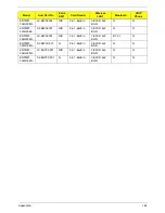
Model
Acer Part No
RO
Country
Description
ENTM89-
522G16Mn
S2.BJZ02.001
WW
WW
ENTM89-522G16Mn W7HP64BWW2
N11PGV2H1GBCbk_3V3 1*2G/160/6L2.2/
5R/CB_bgn_1.3C_GEb_EN11
ENTM89-
332G16Mn
S2.BJ302.001
WW
WW
ENTM89-332G16Mn W7HP64BWW2
PARK_XT512Cbb 1*2G/160/6L2.2/5R/
CB_bgn_1.3C_GEb_EN11
ENTM89-
433G50Bn
S2.BJ202.002
WW
WW
ENTM89-433G50Bn W7HP64BWW2
UMACbk_3 1G+2G/500_L/6L2.2/5R/
CB_bgn_1.3C_GEb_EN11
ENTM89-
433G50Bn
S2.BJ202.003
WW
WW
ENTM89-433G50Bn W7HP64BWW2
UMACbk_3 2G+1G/500_L/6L2.2/5R/
CB_bgn_1.3C_GEb_EN11
ENTM89-
332G16Mn
S2.BJ202.001
WW
WW
ENTM89-332G16Mn W7HP64BWW2
UMACbb 1*2G/160/6L2.2/5R/
CB_bgn_1.3C_GEb_EN11
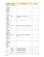
Model
Acer Part No
RO
CPU
LCD
VGA
Chip
VRAM 1
Memory
1
ENTM89-
522G16Mn
S2.BJZ02.001
WW
Ci5520M
NLED15.6
WXGAG
N11PGV
2H
1G-
DDR3
(64*16*8)
SO2GBIII
10
ENTM89-
332G16Mn
S2.BJ302.001
WW
Ci3330M
NLED15.6
WXGAG
PARK_X
T
512M-
DDR3
(64*16*4)
SO2GBIII
10
ENTM89-
433G50Bn
S2.BJ202.002
WW
Ci5430M
NLED15.6
WXGAG
UMA
N
SO1GBIII
10
ENTM89-
433G50Bn
S2.BJ202.003
WW
Ci5430M
NLED15.6
WXGAG
UMA
N
SO2GBIII
10
ENTM89-
332G16Mn
S2.BJ202.001
WW
Ci3330M
NLED15.6
WXGAG
UMA
N
SO2GBIII
10
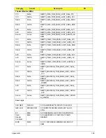
Model
Acer Part No
Memory
2
Memory
3
Memory
4
HDD 1(GB)
HDD
2(GB)
ODD
ENTM89-
522G16Mn
S2.BJZ02.001
N
N
N
N160GB5.4
KS
N
NSM8X
S
ENTM89-
332G16Mn
S2.BJ302.001
N
N
N
N160GB5.4
KS
N
NSM8X
S
ENTM89-
433G50Bn
S2.BJ202.002
SO2GBI
II10
N
N
N500GB5.4
KS
N
NBDCB
4XS
ENTM89-
433G50Bn
S2.BJ202.003
SO1GBI
II10
N
N
N500GB5.4
KS
N
NBDCB
4XS
ENTM89-
332G16Mn
S2.BJ202.001
N
N
N
N160GB5.4
KS
N
NSM8X
S
Summary of Contents for TM86 Series
Page 6: ...VI ...
Page 10: ...X Table of Contents ...
Page 15: ...Chapter 1 5 System Block Diagram ...
Page 62: ...52 Chapter 3 4 Remove one 1 screw from the 3G module 5 Lift the 3G card from the slot ...
Page 73: ...Chapter 3 63 3 Disconnect the following four 4 cables from the Mainboard A B C D ...
Page 78: ...68 Chapter 3 5 Lift the Right Speaker Module clear of the upper cover ...
Page 83: ...Chapter 3 73 5 Lift the card reader board clear of the device ...
Page 85: ...Chapter 3 75 5 Lift the USB board clear of the device ...
Page 92: ...82 Chapter 3 5 Carefully lift the Thermal Module clear of the Mainboard ...
Page 101: ...Chapter 3 91 5 Turn the board over and disconnect the cable ...
Page 103: ...Chapter 3 93 4 Lift the LCD Panel clear of the module ...
Page 105: ...Chapter 3 95 5 Disconnect the LVDS cable from the panel ...
Page 107: ...Chapter 3 97 5 Lift the microphone set clear of the panel ...
Page 114: ...104 Chapter 3 4 Replace six 6 securing screws three on each side of the LCD Panel brackets ...
Page 126: ...116 Chapter 3 6 Connect the LVDS cable and lock the connector 7 Connect the microphone cable ...
Page 131: ...Chapter 3 121 4 Replace the FFC and press down as indicated to secure it to the Upper Cover ...
Page 187: ...Chapter 6 177 ...
Page 188: ...Appendix A 178 Model Definition and Configuration Appendix A ...
Page 212: ...202 Appendix C ...
Page 216: ...206 ...


