Appendix B
191
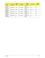
VRAM
1GB
SAMSUNG
VRAM SAMSUNG GraPhic DDRIII 800 1Gb
K4W1G1646E-HC12 LF
VR.1GB0B.006
1GB
HYNIX
VRAM HYNIX GraPhic DDRIII 800 1Gb
H5TQ1G63BFR-12C LF
VR.1GB0G.004
1GB
AMD
VRAM ATI GraPhic DDRIII 800 1Gb
23EY2387MA12-SZ LF+HF
VR.1GB0T.002
512MB
SAMSUNG
512MB
HYNIX
512MB
AMD
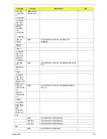
NB ChiPset
PCH
INTEL
S IC BD82HM57 QMNS B3 FCBGA 1071 PCH
PCH
INTEL
S IC BD82HM55 QMNT B3 FCBGA 1071 PCH
KI.G5501.002
PCH
INTEL
S IC BD82HM55 SLGZS B3 FCBGA 1071 PCH
KI.G5501.002
AdaPter
65W (UMA)
DELTA
AC ADAP DELTA ADP-65JH DBA 65W 3P
AP.06501.026
65W (UMA)
LITE-ON
AC ADAP LITE-ON PA-1650-22AC 65W 3P
AP.06503.024
65W (UMA)
LV5 OBL
HIPRO
AC ADAP HIPRO HP-A0652R3B 1LF 65W 3P
AP.0650A.012
90W
(Discrete)
LV5 OBL
DELTA
AC ADAP DELTA ADP-90CD DBA 90W 3P
AP.09001.027
90W
(Discrete)
LITE-ON
AC ADAP LITEON PA-1900-34AR 90W 3P
AP.09003.021
90W
(Discrete)
LV5 OBL
HIPRO
AC ADAP HIPRO HP-A0904A3 B1LF 90W 3P
AP.0900A.005
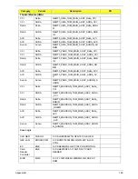
Power Cord
3Pin
Linetek
PWR CORD LP30BX1.8MXLS15 US 3P L
3Pin
I-Sheng
PWR CORD SP305AX1.8MXIS034 SPT-2 BLK
3Pin
WS
PWR CORD WS-001F-2X1.8MXWS-083 3P US
W
Battery
6CELL2.2
SANYO
BATT SA SA 3S2P 4.4AH 7 0C9 0FA
BT.00603.111
6CELL2.2
SONY
BATT SY SY 3S2P 4.4AH 7 0C9 0FA
BT.00604.049
6CELL2.2
PANASONIC
BATT PA PA 3S2P 4.4AH 7 0C9 0FA
BT.00605.062
6CELL2.2
SAMSUNG
BATT SM SM 3S2P 4.4AH 7 0C9 0FA
BT.00606.008
6CELL2.2
SIMPLO
(PANASONIC)
BATT SP PA 3S2P 4.4AH 7 0C9 0FA
BT.00607.125
6CELL2.2
SIMPLO
(LGC)
BATT SP LG 3S2P 4.4AH 7 0C9 0FA
BT.00607.126
6CELL2.2
SIMPLO
(SAMSUNG)
BATT SP SM 3S2P 4.4AH 7 0C9 0FA
BT.00607.127
K/B
DARFON
KB 9J.N1H82 DARFON INT'E 09F
KB.I170E.001
Chicony
KB MP-09B2 CHICONY INT'E 09F
Category
Vendor
Description
PN
Summary of Contents for TM86 Series
Page 6: ...VI ...
Page 10: ...X Table of Contents ...
Page 15: ...Chapter 1 5 System Block Diagram ...
Page 62: ...52 Chapter 3 4 Remove one 1 screw from the 3G module 5 Lift the 3G card from the slot ...
Page 73: ...Chapter 3 63 3 Disconnect the following four 4 cables from the Mainboard A B C D ...
Page 78: ...68 Chapter 3 5 Lift the Right Speaker Module clear of the upper cover ...
Page 83: ...Chapter 3 73 5 Lift the card reader board clear of the device ...
Page 85: ...Chapter 3 75 5 Lift the USB board clear of the device ...
Page 92: ...82 Chapter 3 5 Carefully lift the Thermal Module clear of the Mainboard ...
Page 101: ...Chapter 3 91 5 Turn the board over and disconnect the cable ...
Page 103: ...Chapter 3 93 4 Lift the LCD Panel clear of the module ...
Page 105: ...Chapter 3 95 5 Disconnect the LVDS cable from the panel ...
Page 107: ...Chapter 3 97 5 Lift the microphone set clear of the panel ...
Page 114: ...104 Chapter 3 4 Replace six 6 securing screws three on each side of the LCD Panel brackets ...
Page 126: ...116 Chapter 3 6 Connect the LVDS cable and lock the connector 7 Connect the microphone cable ...
Page 131: ...Chapter 3 121 4 Replace the FFC and press down as indicated to secure it to the Upper Cover ...
Page 187: ...Chapter 6 177 ...
Page 188: ...Appendix A 178 Model Definition and Configuration Appendix A ...
Page 212: ...202 Appendix C ...
Page 216: ...206 ...


