©2020 PACE Inc., Vass, North Carolina,
All Rights Reserved
Page
23
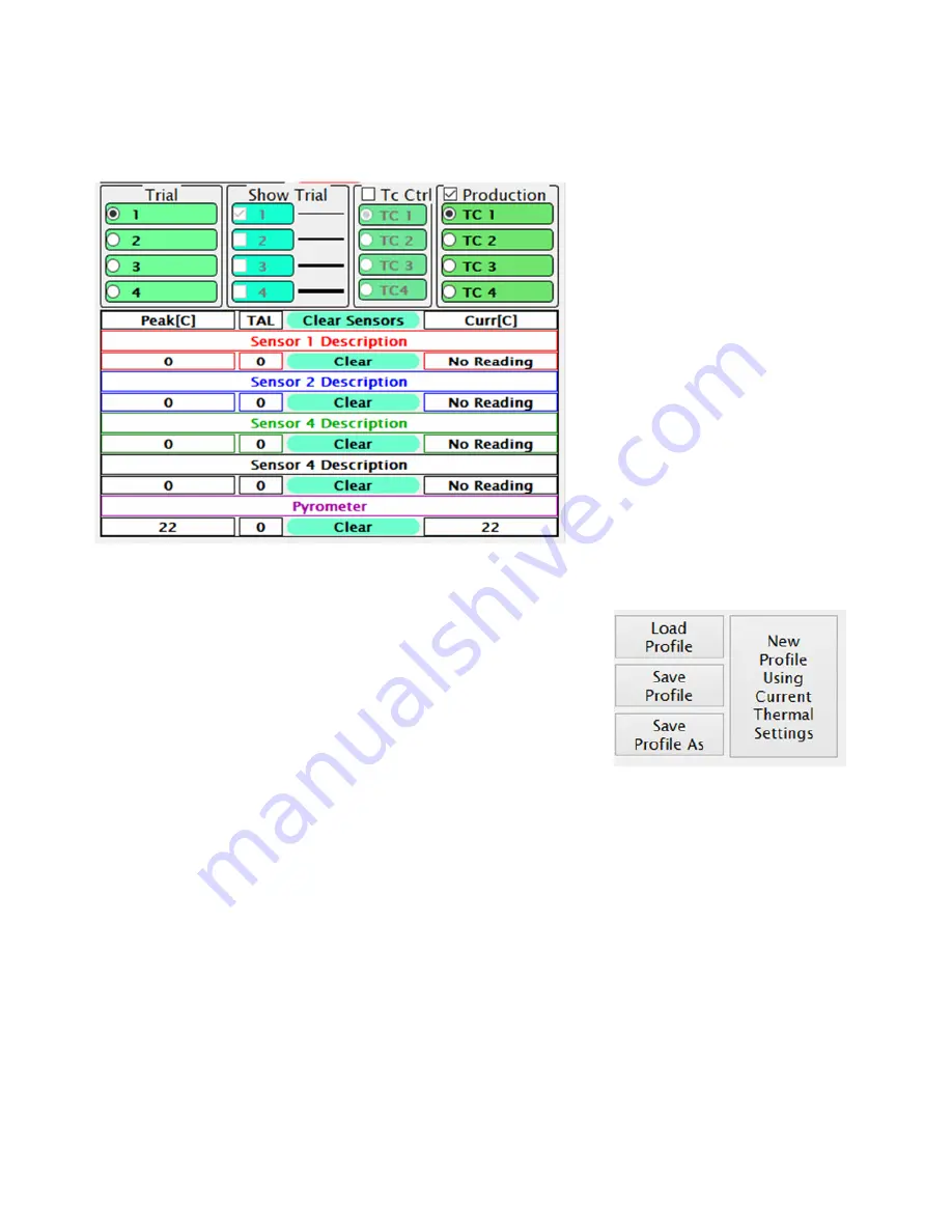
During the profile development process, up to 4 “trial runs” can be made/viewed for comparing and
contrasting how well different settings work on a given application. The information displayed in each trial run
can be altered using the buttons and check boxes above the temperature sensor readouts.
•
Trial Number – This column
designates which trial run is currently
active for editing or being saved to the
finished profile for reference in
production runs.
•
Show Trial – Select which trial run
profile graphs are currently visible.
•
Tc Ctrl –Use this to select one of the
external thermocouple sensors instead
of the pyrometer for controlling the
temperature during a profile run.
•
Production – Select external
thermocouple temperature graph(s) to
be visible as reference during production
runs of the profile.
Sensor descriptions can be changed by the profile developer to better indicate to the production user where
the sensors were located during profile creation.
Your new IR machine will come with default installation and
removal profiles. These can be used as starting points for new custom
profiles. The IR software will memorize the distance traveled by the
heater head during some parts of an installation or removal process. The
included default profiles do not have any distances stored. When altering
any other pre-existing profile to work with different components, after
loading the profile you must clear the distance settings with the “New
Profile” button or the heater head could crash.
Following is a sample outline of steps needed to develop an installation profile by doing a new
component installation. The process is essentially the same as doing a production run, except with the ability to
make changes.
1. Turn on the IR machine and the PC, then start the PACE software.
2. Navigate to the Developer Mode screen if not already there.
3. Load a profile using the Load Profile button.
4. Install the proper vacuum pick.
5. Click “Start Process” and follow the onscreen instructions which will guide you through the
following steps.
6. Place the PCB between the arms of the board holder and position the board so the red
laser point is roughly in the center of the component placement site then tighten the
retention screw.
7. Apply flux to the board if needed, and attach any thermocouples desired for additional
process monitoring. Adjust the board support to the middle of the board.
8. Place the component in the mounting plate on top of the camera housing. Click “okay”.
9. The BGA workstation will pick up component. If the vacuum pick fails to pick up the
component, reset the component in the nest and click “Retry”.


