©2020 PACE Inc., Vass, North Carolina,
All Rights Reserved
Page
14
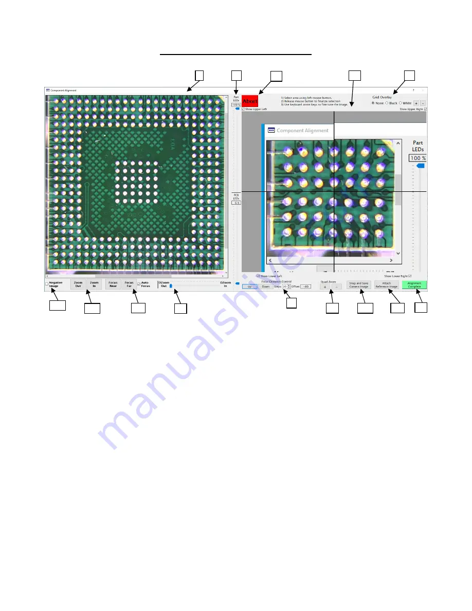
The Component Alignment Screen
I.
Main Camera Image
– This is the main camera viewport. The viewport shows a combination of looking
down at top of the board and looking up at bottom of the component. This allows the user to align the
solder balls or leads of a component with the corresponding pads on the board.
II.
LED controls
– The two sliders in this column control LED intensity for the light shining up at the
component part and down at the PCB.
III.
Abort
– Pressing this button will abort the operation and return to the previous screen while also
returning the heater head and camera arm to their home positions.
IV.
Quad-Field Imaging
– These four viewports, or quadrants, allow portions of the Main Camera Image to
be viewed in more detail when fine tuning alignment without the need for adjusting the Main Camera
Image. Use this feature by left-clicking a point in the Main Camera Image and the associated Quad-
Field viewport will center on that point. Each quadrant can be turned on/off individually.
V.
Grid Overlay
– When selected, this will show grid lines in the Quad-Field Imaging viewports. The grid
lines can be set to black or white, and the +/- buttons will adjust the grid size.
VI.
Alignment Complete
– Once the component has been properly aligned, click this button to proceed.
VII.
Attach Reference Image
– Only appears in Developer Mode. Allows the developer to link saved
images to a profile for reference during production runs.
VIII.
Snap and Save Camera Image
– Allows the user to capture and save images.
IX.
Quad Zoom
– Use this to increase/decrease digital magnification of the Quad-Field Imaging.
I
II
VII
III
IV
VI
V
XII
VIII
IX
X
XI
XIV
XIII


