6
Installation Heatpump PHP 2016
IN
OUT
Drawing no: M12399-1
2016-03-02 ASA
R
1
3
7
8
9
10
2
6
9
9
9
9
9
11
5
4
5
L
GREEN
/
YELLOW
BLUE
BROWN
ASA 2016-11-08
P2
P1
N
L
N
BLUE
GREY
BLACK
T
N
S
R
GREEN
/
YELLOW
BEIGE
T
N
R
S
Heat pump PVP Inverter
MA20-14E rev 1
ENGLISH
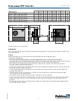
1. Skimmer
2. Main drain
3. Inlet
4. JetSwim
5. Light
6. Circulation pump
7. Filter
8. Heat pump
9. Check valve
10. Drain
11. Drain
Pipe installation
Heat pump must always be connected with a fixed PVC pipe Ø50 or a bypass kit (recommended by Pahlén ).
The pipes may need to be relieved, so that the connections do not have too much burden (breakout force can damage the
heat exchanger).
Any tightening of the coupled connections to the heat pump should be made by hand (tools can damage connections).
To protect the heat pump from dirt and snow it is optimal to place it on a base or stand above the ground level.
NOTE! The pipe length between the pump and the pool should not be more than 10 meters.
Install the supplied drain connection down through the holes in the heat pump’s base. Connect it to the following drainage hose
and make sure that wastewater and condensate are drained from the heat pump.
Electric installation
Electric installations must be performed by a qualified electrician in accordance with applicable regulations.
Installation must be preceded by installation of a residual current device and maintenance switch.
Never start the pump until all wiring and re-checking are performed.
PVP10
PVP11
PVP13
PVP17
PVP28
Maintenance switch
Rated current
11A
12A
13A
16A
9A
RCD
Leakage current
30mA
30mA
30mA
30mA
30mA
Маx.ström
9A
10A
11A
13.5A
7A
Fuse
13A
13A
13A
16A
10A
Power cable
3x2,5 mm²
3x2,5 mm²
3x2,5 mm²
3x2,5 mm²
5x2,5 mm²
NOTE! The above data applies to the electric cable ≤ 10 m. If the cable is longer than 10 meters the cable section must be
prolonged.
Before connecting power supply
•
Check that installation and pipe connections are like on the diagram.
•
Check that electrical wires are connected according to the diagram.
Check earth connection carefully.
•
Check that the pump air inlet and outlet are not blocked.
Wiring diagram
Mainte-
nance
switch
Earth
Fuse
Distribution box
Power cord
Earth fault
relay
Connection in the heat pump
220-240V
1-phase/50Hz
Option
P1: not used P2: not used
GREEN/YELLOW
BLUE
BROWN
Mainte-
nance
switch
Earth
Fuse
Distribution box
Power cord
Earth fault
relay
Connection in the heat pump
400V
3-phase/50Hz
GREEN/YELLOW
BLUE
BLACK
GREY
BEIGE


