12
Gateway Autodos
MA60-26E
ENGLISH
E10075-0
150526 ASA
Autodos M1 / M2 / M3
GATEWAY
netbiter EC220
Inkopplingsschema Gateway EC220 - Autodos
25
24
23
22
21
20
19
18
14 15 16 17
13
Modbus RTU
Tx
-
Tx
+
Rx
-
Rx
+
GND
Tx
term
Rx
term
Rx
term
COM
B
A
Rs232
SIM
COM
NO
COM
Dl
2
Dl
1
COM
Al
1
Al
2
COM
OUT
GND
+Vdc
DI
AI
A0
RS 485
Strappings
Gateway EC220
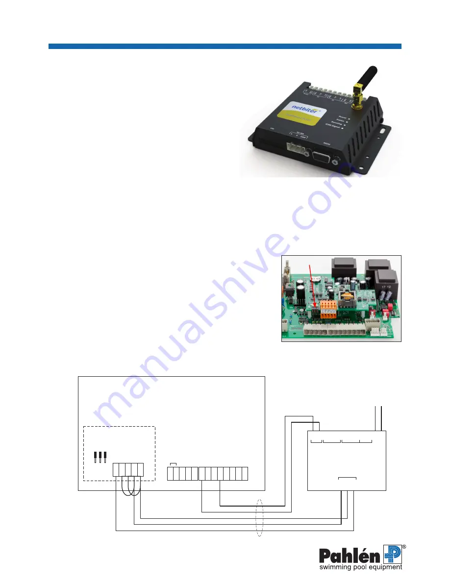
The unit is preconfigured, and the accompanying description from
the manufacturer is normally not needed.
Login information and additional description of the cloud service is provided separately.
The Gateway EC220, item no. 416230, is shipped with documentation,
registration data, and an AC adapter.
Note that the Gateway module need not be installed immediately adjacent
to the Autodos M. It can be installed in a separate area with access to
mobile data coverage.
Note that this product is not IP rated. If it is to be installed in an engine
room in an exposed environment, it should be placed inside a cabinet
whose IP rating corresponds to what is required in that environment.
Safety
Before making any electrical connections or performing other work on the Autodos and/or the EC220, the unit must be
disconnected from electrical power.
Installation of the Gateway EC220
1. Install the EC220 on a solid support in an IP-rated area.
2. Connect the supplied antenna.
3. Disconnect the Autodos M from electrical power.
4. Connect a 5-lead cable (5 x min 0,25 mm2) between the EC220 and the Autodos per the connection diagram:
Tx - / Rx - (bridged)
Tx + / Rx + (bridged)
Tx + connects to A on the EC220
Tx – connects to B on the EC220
GND connects to COM on the EC220
Leave the strappings for Modbus addressing in position.
Standby inputs 18 and 21 connect to relay outputs NO and COM, respectively,
on the EC220.
5. Connect the AC adapter’s single-wire to the EC220:
(+ red) to +VDC
(- white) to GND
6.
Connect the AC adapter to 230V AC and start the Autodos M.
The display will initially show Modbus information, then revert to a countdown
from 60 seconds
Electrical connection diagram
12 VDC
5 x min 0,25 mm
2
Modbus RTU
9600 band, Parity None
Flow meter / 16 VDC PNP
input
PNP
in level monitor (alarm when the input is closed)
Flow meter / NPN in flow monitor
PNP
in STDBY
Power output 2 (redox/chlorine) 4–20mA
Power output 1 (pH) 4–20mA
Flow
meter / - GND power outputs
Temperature sensor - GND temerature sensor
Two-wire communication with PC
Relay
D1
A1
A0


