background image

17

Gateway Autodos

MA60-26R

РУССКИЙ

E10076-0

150527 ASA

Autodos M1 / M2 / M3

GATEWAY

netbiter EC310

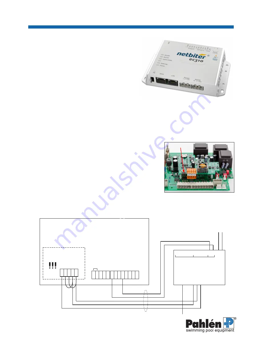
Inkopplingsschema Gateway Ec310 - Autodos

25

24

23

22

21

20

19

18

14 15 16 17

13

Tx

-

Tx

+

Rx

-

Rx

+

GND

Tx

term

Rx

term

Rx

term

COM

B

A

GND

PE

Al

4

COM

Al

3

Al

2

Al

1

D2-

D2+

D1-

D1+

COM

-V

dc

+V

dc

RS 485

W
AN

LAN

RS 432

Tx

Rx

NO

РУССКИЙ

Плата Modbus установлена на нижней плате

Gateway EC310

Это устройство уже предварительно конфигурировано, и прилагаемое к 


нему описание от изготовителя, как правило, не используется.

Данные для входа и дополнительное описание облачного сервиса 


поставляются отдельно.
В комплект поставки EC310 с артикулом 416231 входит необходимая


документация, регистрационные данные и сетевой адаптер.

Следует отметить, что модуль Gateway не должен устанавливаться


 рядом с Autodos М. Его можно установить в отдельном 


пространстве, в котором имеется доступ к сети Ethernet/WAN.
Пожалуйста, имейте в виду, что это изделие не классифицировано


по IP. Если его нужно установить в машинном отделении с 


незащищенной средой, его следует установить в шкафу, имеющем


класс IP, соответствующий этой среде.

Безопасность

При выполнении электрического подключения или выполнении других работ на Autodos и/или ЕС310 необходимо 

отключать напряжение.

Установка Gateway EC310

1.  

Установите EC310 на прочном основании в помещении, имеющем классификацию IP.

2.  

Отключите питание Autodos M.

3.  

Подключите пятижильный кабель (5 x мин. 0,25 мм2) между EC310 и 


Autodos согласно схеме соединений: 


Tx – / Rx –: соединение перемычкой


Tx + / Rx +: соединение перемычкой


Tx + присоединяется к т. A на EC310


Tx – присоединяется к т. В на EC310


GND присоединяется к COM на EC310


Перемычки для адресации Modbus должны остаться на месте.


В режиме ожидания вход 18 или  21 подключен соответственно к выходу 


реле NO и COM на EC310

4.   Подключите отдельный провод сетевого адаптера к EC310:


(+) к [+]


(–) к [–]

5.   Подключите вывод Ethernet в помещении к WAN/Ethernet на EC310.
6.   Подключите сетевой адаптер к сети 230 В перем. тока и запустите Autodos М. Сначала на дисплей выводятся 

данные Modbus, затем начинается обратный отсчет от 60 секунд.

Схема электрических соединений

Клеммы

5 x мин. 0,25 мм

2

12 В пост. тока

WAN / Ethernet

Modbus RTU

Полоса 9600, контроль 

четности отсутствует

Да

тчик т

емпера

ту

ры

Да

тчик т

емпера

ту

ры - GND

Дв

ухпров

одная св

язь с PC

Аналоговый 

вход

DI / Импу-

льсный вход

Реле Питание 

Изм

ери

те

ль расх

ода

 / - GND, т

ок

овые вых

оды

Вых

одн

ой т

ок

 1 (pH) 4–20 м

А

Вых

одн

ой т

ок

 2 (ре

до

кс/хл

ор) 4–20 м

А 

Вх

од PNP

, ре

жим

 STDBY

Изм

ери

те

ль расх

ода

 / вх

од NPN, ре

ле

 расх

ода

PNP

, ре

ле у

ровня


(п

ри

 зак

рыт

ом вх

оде

 по

да

ет

ся

 сигнал трев

оги)

Изм

ерит

ель расх

ода / 16 В п

ост

. т

ок

а, вх

од PNP

 В

хо

д

Перемычки

Summary of Contents for EC220

Page 1: ...allationsanvisning User manual Инструкция MA60 26 rev 0 2015 Surface treatment part of ISO 2768 1 The tolerance clas E Box 728 SE 194 27 Upplands Väsby Phone 46 8 59411050 Fax 46 8 59 This document and its contents are the exclusive property of Pahléns and may not be copied reproduced transmitted or communicated to a third party or used for any purpose without written permission 127 20 46 160 80 S...

Page 2: ......

Page 3: ... är utrustad med genom att trycka på och hålla inne knapparna Alarm high Alarm low Autodosens högra display A visar nu aktuell programversion Registrering Med produkten medföljer dokumentation med registreringsuppgifter De är värdehandlingar och skall förvaras därefter Fyll i dessa uppgifter i medföljande registreringsunderlag sista sidan Komplettera med era installations kontakt projekt och syste...

Page 4: ...ler locket med displayen på på styrboxen i Autodos M 4 Lossa försiktigt bandkontakten på bottenkortet 5 Modbus kortet har en kontakt samt 3 st plastclips på undersidan Placera dessa i läge mot de anvisade hålen i Autodosens bottenkort Montera Modbus kortet försiktigt Säkerställ att kontakten bottnar och plastclipsen låser 6 Modbus är nu monterat på Autodos M s bottenkort Här ska Modbus kortet fäst...

Page 5: ...rbete med Autodos och eller EC310 skall anslutningsspänningen brytas Installation Gateway EC310 1 Montera EC310 mot ett fast underlag i ett IP klassat utrymme 2 Bryt strömmen till Autodos M 3 Anslut en femledad kabel 5 x min 0 25 mm2 mellan EC310 och Autodos enligt kopplingsschema Tx Rx överkopplas Tx Rx överkopplas Tx kopplas till A hos EC310 Tx kopplas till B hos EC310 GND kopplas till COM hos E...

Page 6: ...risk inkoppling eller annat arbete med Autodos och eller EC220 skall anslutningsspänningen brytas Installation Gateway EC220 1 Montera EC220 mot ett fast underlag i ett IP klassat utrymme 2 Anslut medföljande antenn 3 Bryt strömmmen till Autodos M 4 Anslut en femledad kabel 5 x min 0 25 mm2 mellan EC220 och Autodos enligt kopplingsschema Tx Rx överkopplas Tx Rx överkopplas Tx kopplas till A hos EC...

Page 7: ...tiveringskod activation code Endast EC220 Telefonnr phone mobile number Endast EC220 SIM kort nr SIM card number Projektuppgifter Projektnamn företag simanläggning hotell SPA etc Systemnamn t ex namn på poolen Autodosmodell Serienr Autodos Elektrodkonfiguration Doseringsutrustning klor Doseringsutrustning syra Användaruppgifter administratör Serviceföretag eller liknande Kontaktperson Mobiltelefon...

Page 8: ......

Page 9: ...mmunications module must be installed in your Autodos M Check system software Check the system software version in your Autodos M by pressing and holding the Alarm high Alarm low buttons The Autodos s right hand display A shows the current software version Registration The product is shipped with documentation including registration data These are valuable documents and should be stored with appro...

Page 10: ...t hold the cover with display on the Autodos M control box 4 Carefully loosen the strip connector on the bottom card 5 The Modbus card has one connector and 3 plastic clips on the underside Place these in position opposite the specified holes in the Autodos s bottom card Carefully install the Modbus card Ensure that the connection is firm and the plastic clips lock in place 6 The Modbus is now ins...

Page 11: ...e Autodos and or the EC310 the unit must be disconnected from electrical power Installation of the Gateway EC310 1 Install the EC310 on a solid support in an IP rated area 2 Disconnect the Autodos M from electrical power 3 Connect a 5 lead cable 5 x min 0 25 mm2 between the EC310 and the Autodos per the connection diagram Tx Rx bridged Tx Rx bridged Tx connects to A on the EC310 Tx connects to B o...

Page 12: ...forming other work on the Autodos and or the EC220 the unit must be disconnected from electrical power Installation of the Gateway EC220 1 Install the EC220 on a solid support in an IP rated area 2 Connect the supplied antenna 3 Disconnect the Autodos M from electrical power 4 Connect a 5 lead cable 5 x min 0 25 mm2 between the EC220 and the Autodos per the connection diagram Tx Rx bridged Tx Rx b...

Page 13: ...mber on the Gateway Activation code EC220 only Mobile telephone number EC220 only SIM card number Project declaration Project name company swimming complex hotel spa etc System namne e g name of pool Autodos model Autodos serie number Electrode configuration Dosing equipment chlorine Dosing equipment acid User information administrator Service company or similar Contact person Mobile telephone num...

Page 14: ......

Page 15: ...16231 Modbus RTU Коммуникационный модуль OPC Артикул 416209 Необходимые условия Ваш Autodos M должен иметь системное ПО версии 5 6 или более поздней При использовании более старой версии ПО обращайтесь по адресу support pahlen se В вашем Autodos M должен быть установлен коммуникационный модуль Modbus RTU Проверьте системное ПО Проверьте какая версия программного обеспечения установлена в Autodos М...

Page 16: ... коробке управления Autodos M 4 Осторожно отсоедините ленточный разъем на нижней стороне платы 5 Плата Modbus имеет один разъем и 3 пластиковых зажима на нижней стороне Поместите их против соответствующих отверстий на нижней плате Autodos Осторожно установите плату Modbus Убедитесь что разъем полностью вошел и пластиковые зажимы защелкнулись 6 Теперь плата Modbus закреплена на нижней плате Autodos...

Page 17: ...310 на прочном основании в помещении имеющем классификацию IP 2 Отключите питание Autodos M 3 Подключите пятижильный кабель 5 x мин 0 25 мм2 между EC310 и Autodos согласно схеме соединений Tx Rx соединение перемычкой Tx Rx соединение перемычкой Tx присоединяется к т A на EC310 Tx присоединяется к т В на EC310 GND присоединяется к COM на EC310 Перемычки для адресации Modbus должны остаться на месте...

Page 18: ...220 на прочном основании в помещении имеющем классификацию IP 2 Подсоедините антенну входящую в комплект оборудования 3 Отключите питание Autodos M 4 Подключите пятижильный кабель 5 x мин 0 25 мм2 между EC220 и Autodos согласно схеме соединений Tx Rx соединение перемычкой Tx Rx соединение перемычкой Tx присоединяется к т A на EC220 Tx присоединяется к т В на EC220 GND присоединяется к C0M на EC220...

Page 19: ... Только для EC220 номер СИМ карты Данные проекта Название проекта компания бассейн отель СПА и т д Наименование системы например название бассейна Модель Autodos Серийный номер Autodos Конфигурация электродов Оборудование для дозирования хлора Оборудование для дозирования кислоты Данные пользователя администратор сервисная компания или аналогично Контактное лицо Номер мобильного телефона Электронн...

Reviews: