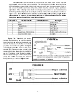
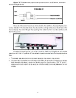
background image

Figure "C"

 illustrates the proper hookup of wires to an on/off switch, which will 

control a single device. 

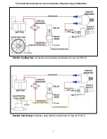
Once all of the wires have been connected to the switches, the polyethylene liner 

can be installed.  First decide where the wires will be exiting and make a small hole in the 
liner and pass the wires through the opening, then slide the liner over the switches and 
flush to the panel.   

For dash mounted panels, you must cut a 

¼” x 2 ¼”

 opening for the four switch 

panel or a 

¾” x 2 ¼”

 opening for the six switch panel to allow room for the polyethylene 

liner.   

  The plastic wire ties are for looming and securing the wires to the vehicle.   

  The label sheet included is to identify each switch of its function. Simply peel off the 

label  needed and  place  it  under  the  switch wired  for  that  function.  The "R"  and "L" 
labels are for right and left in the event an on/off/on switch is turned sideways for turn 
signals 


Summary of Contents for 50334

Page 1: ...road 4 Toggle switches Dash Mount w Push Button Start 50336 Off road 6 Toggle switches Dash Mount w Push Button Start Painless Performance Products recommends you the installer read this installation...

Page 2: ...oncerning these instructions please call or email us our contact information can be found at the top of this page or online at www painlessperformance com We sincerely appreciate your business Painles...

Page 3: ...Customizable Switch Panel w 1 label sheet 1 Foam Liner 5 or 7 Toggle Switches o 3 or 5 On Off o 1 On Off On o 1 Off Momentary On 4 or 6 Toggle Switch Boots 1 Ignition Switch 1 Ignition Switch Nut w B...

Page 4: ...using the nut inside the switch boot could damage the shoulders around the boot In order to allow the maximum amount of room for the switch labels line the switch boots up with the flat sides of the h...

Page 5: ...ch This short red wire will then be routed to the second circuit breaker to the left of the start button and the pink wire will be routed out to the ignition coil With this setup you will then have an...

Page 6: ...cidental pushing of the start button from cranking the engine over and creating a hazardous situation Figure A illustrates the proper hookup of wires using an on off on switch when two devices are to...

Page 7: ...er the switches and flush to the panel For dash mounted panels you must cut a 7 x 2 opening for the four switch panel or a 9 x 2 opening for the six switch panel to allow room for the polyethylene lin...

Page 8: ...rations below are some examples of typical relay installations Electric Cooling Fan connection using Painless weatherproof relay kit 30130 Electric Fuel Pump connection using Painless weatherproof rel...

Page 9: ...riginal purchaser to be free from defects in material and workmanship under normal use Painless Performance will repair or replace defective products without charge during the first 12 months from the...

Reviews: