16
Optional Accessories within the TORC Module
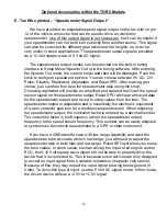
E. Tan Wire printed
– “Speedometer Signal Output”
We have provided an adjustable speed signal output on the tan wire on pin
12 of
the vehicle connector that can be used to drive an electronic
speedometer. Use
of this output signal is not necessary, but it can be helpful if
your speedometer
can not be driven correctly from another source. This signal
can also be
corrected for different gear ratios and tire heights, so it can be
very useful in
some applications. The speedometer output signal is provided
as a 12 Volt
square wave or 5 Volt AC signal.
The speedometer output modes can be
selected via the built-in tuning
interface in Setup Menu>Speedo Out or in the
tuning software. After entering
the Speedo Out menu, the current mode and ratio
will be displayed. Push the
knob to configure speedo out options. You can
choose between 5V AC, 12V
Pulse, Disable, Replicated, Adjustable, and Reset
SPO. After making your
choice, you can then fine tune the speedometer ratio
using the knob.
Choosing replicated will provide an amplified and squared replica of the speed
sensor signal on the speedometer output. Reset SPO will
clear all saved data
for the speedometer output and revert to using values from
the tune. The
speedometer output is adjustable and is essentially the electronic
equivalent
of a ratio corrector gear box for a mechanical speedometer. When
adjusting
the speedometer output, the correction factor is entered as a decimal
number.
The correction factor is the frequency ratio of the speedometer output
frequency to the speed sensor frequency. This number can be easily adjusted
to
synchronize the vehicle speedometer to a GPS or other instrument.
If you have
a 4WD transfer case with low range capability and want the
speedometer to be
accurate while in low range, you will need to adjust the
speedometer ratio in
both high and low range. Reset SPO will allow you to use
the tune values.
In some cases, such as driving the input of an engine control
ECU, the 0-12 Volt
square wave signal will not be able to properly drive the
device that it is
connected to. This is because some devices are only designed
to accept an
input signal from a variable reluctance (magnetic coil) sensor.
Because of this,
they may expect the input signal to swing below ground (0
Volts). To drive this
type of input, use the 5 Volt AC signal mode. In this mode,
the driven device will
see a -2.5V to +2.5V signal.


