


8
ALL MAKES - SPECIFIC CIRCUIT CONNECTIONS
8.1
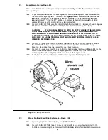
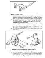
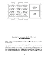
Generator Charging System. See Figure 8-1.
8.1.1 Connect Generator ARMATURE terminal (A) to Voltage Regulator terminal A. Connect Generator
FIELD terminal (F) to Voltage Regulator terminal F. Use 14-gauge wire (color optional) for FIELD
and 12-gauge wire for Armature.
8.1.2 Be sure both the generator and the voltage regulator are securely grounded. The voltage regulator
may have a terminal for this purpose (labeled "G") or you may have to ground the regulator case.
8.1.3 Connect ENGINE SECTION wire #915 (BLK) to Voltage Regulator terminal B.
8.1.4 Insulate and stow ENGINE SECTION wire #914 (BLU).
Figure 8-1 Generator Charging System
8.2
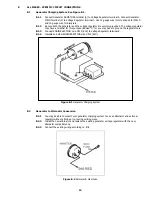
Generator to Alternator Conversion
8.2.1 You may be able to convert your generator charging system to use an alternator and external
regulator without altering or re-routing existing wires.
8.2.2 Install the new alternator and replace the existing generator voltage regulator with the new,
alternator compatible one.
8.2.3 Connect the existing wiring according to 7.1
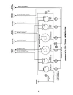
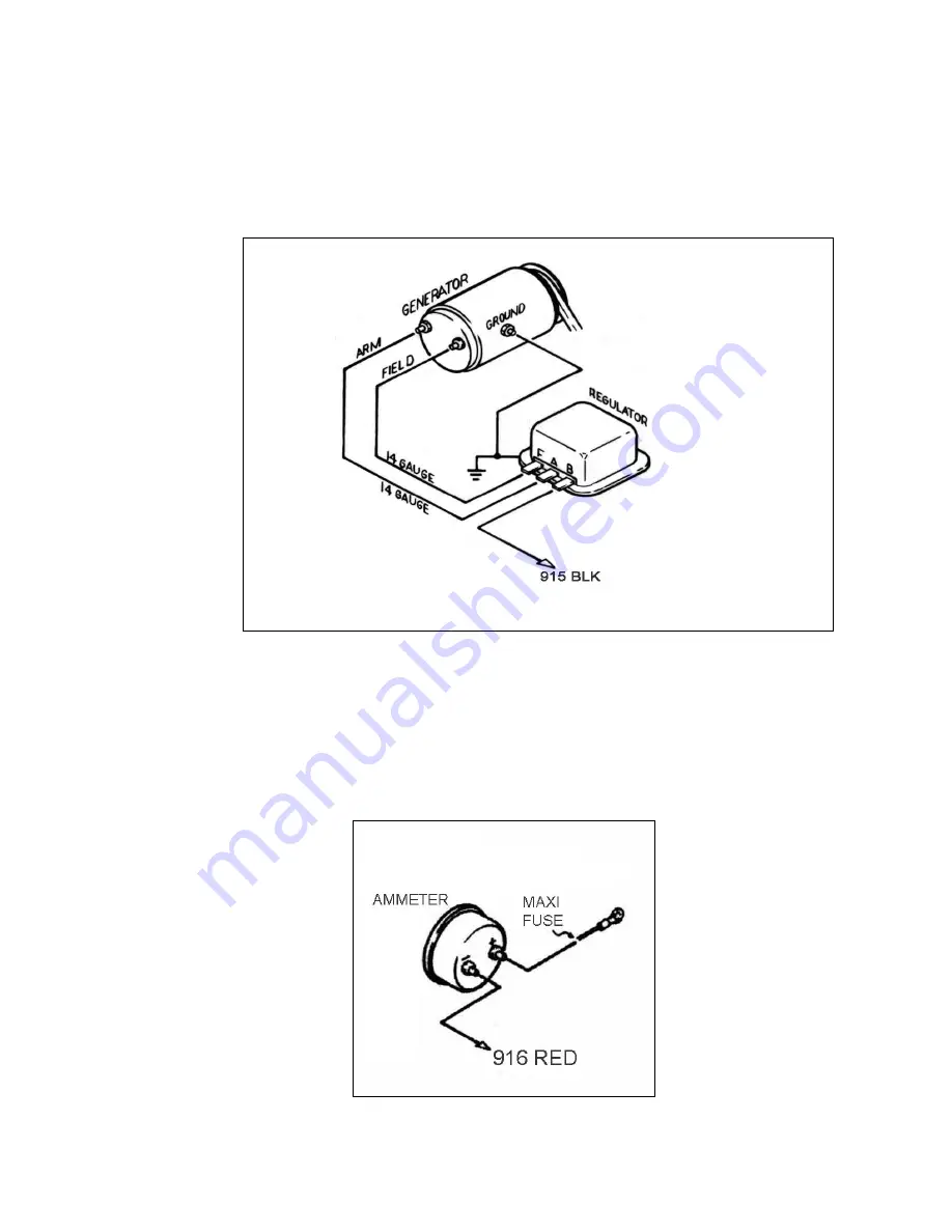
Figure 8-2 Ammeter & Maxi Fuse
13


