


8.7
Instrument Panel Wiring
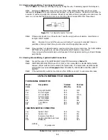
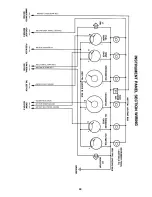
8.7.1 Connect the wires of the INSTRUMENT PANEL SECTION as indicated in Table 9-2. Insulate and
stow any wires you do not use.
8.7.2
Connect a jumper from wire #935 (BLK) to all Gauges' power or “I” terminals. Connect a jumper
from wire #930 (ORN) to all Gauges' Instrument Lighting terminals. Connect a jumper to all
Gauges' Ground terminals and connect to Chassis Ground.
For termination, see 8.10.3
8.8
Brake Light Switch
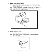
8.8.2
Connect wires #917 (PNK) and #918 (WHT) to the Brake Light Switch wherever it may be
mounted. These wires are in ENGINE SECTION A
8.8.3
The Third Brake Light wire is pre-connected on the Switch end. Connect TAIL SECTION wire #950
(ORN) to the Third Brake Light if applicable.
8.9
Tail Section Wiring
8.9.2
Connect the wires of the TAIL and TURN SIGNAL SECTIONS as indicated in Table 9-2 with the
exception of #918 (WHT), #948 (BRN), #949 (GRN) and #950 (ORN).
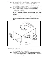
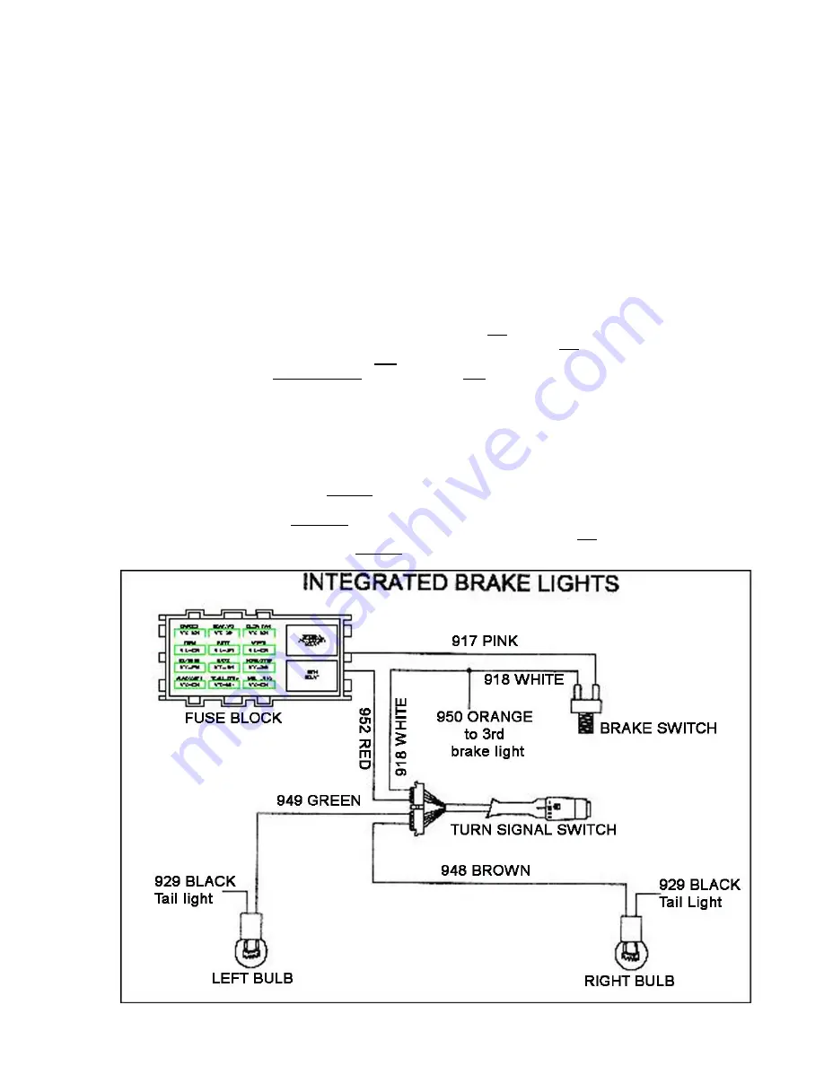
8.9.3
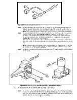
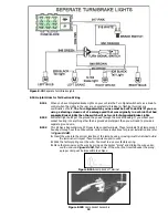
These 4 wires will be connected according to one of the diagrams shown in BELOW. Which
diagram you will use depends on whether or not you have one bulb on each side of the vehicle
that is for the brake/tail and Turn Signal Lights (this is referred to as integrated lights) or you
have more than one bulb on each side and the Brake and Turn Signal Lights are hooked to
different bulbs (referred to as separate Brake/Turn Lights).
Note A:
If you have Integrated Brake Lights you must use bulbs that have two (2) filaments in
them such as in an 1157 bulb.
Note B:
The three wires shown in these diagrams are connected to the "brighter" of the two
filaments when using a two-filament bulb (the Tail Lights are usually connected to the
"Dimmer" filament). The Tail Lights, License Plate Lights, Reverse Lights, etc. are not
shown on the diagrams for clarity.
Note C:
In the separate Brake Light diagram the arrangement shown is only one of several ways
to wire a vehicle. The important thing is that the Brake and Turn Signal Lights use
completely separate bulbs.
Note D
:
The white wire (#918) in the Turn Signal section will not be connected to the turn switch
when using separate turn lights and brake lights. See figure 8-7B
Figure 8-7A Integrated Brake Lights 17


