background image


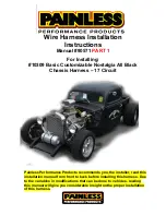
Wire Harness Installation  

Instructions  

Manual #90571 

PART 1 


For Installing: 

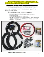
#10309 Basic Customizable Nostalgia All Black 

Chassis Harness 

– 17 Circuit 


Painless Performance Products recommends you, the installer, read this 
installation manual from front to back before installing this harness. Due 
to the variables in modifications that can be done to vehicles, reading 
this manual will give you considerable insight on the proper installation 
of this harness.


Summary of Contents for 10309

Page 1: ...s Harness 17 Circuit Painless Performance Products recommends you the installer read this installation manual from front to back before installing this harness Due to the variables in modifications th...

Page 2: ...corrections or improvements that can be made If you have found any errors or omissions or if you simply have comments or suggestions concerning these instructions please write us at the address above...

Page 3: ...ing the removal process avoid making any unnecessary cuts This harness is universal in nature meaning all ends are left open to allow you to cut wire to length and install the appropriate connection T...

Page 4: ...Headlight 26 Headlight w Pigtails 28 Left Turn Park Light 29 Horn Right Turn Park Light Right Headlight 31 ENGINE IGNITION SECTION Coil ignition 32 Ballast Bypass 33 Tachometer 35 Engine Sending Units...

Page 5: ...30 HEADLIGHT SECTION SCHEMATIC 34 COIL CONNECTIONS diagram BALLAST RESISTOR CONNECTIONS diagram MSD CONNECTIONS diagram 35 HEI COIL ON CAP CONNECTIONS photo 38 ENGINE SECTION SCHEMATIC 39 CHARGE INDIC...

Page 6: ...of this manual are pretty straight forward and easy to follow The install portions are noted with a round bullet note as seen here Individual components and sections are labeled with printed tags for...

Page 7: ...in this kit If you find that anything is missing or damaged please contact the dealer where you obtained the kit or Painless Performance at 800 423 9696 The Painless Wire Harness Kit should contain t...

Page 8: ...to have shorter lengths than the fuse block harness but still provide ample length for just about any install These shorter lengths result in less waste when you route and cut these wires to length SM...

Page 9: ...connections to an HEI distributor headlights and factory style alternator If none can be found locally these crimpers can be found using Painless part 70900 A good set of wire strippers are required t...

Page 10: ...also depends a great deal on fuse block mounting location and to the extent you want to secure and conceal the harness This aspect will be more prominent in the ENGINE SECTION wiring where much of th...

Page 11: ...short enough that only insulation is crimper by Strap 2 The photo to the left best demonstrates this Using the appropriate jaw on the crimpers crimp Strap 1 The appropriate jaw depends on the wire ga...

Page 12: ...re installed like turn signal or tail light housings Components with plastic housings or non conductive housings like headlights which are glass get their grounds through wires from the chassis harnes...

Page 13: ...round and back to the battery When this happens things that should not have power receive power coming from the park light bulb Since the turn signal wire also goes to the bulb the current will travel...

Page 14: ...14...

Page 15: ...How a flasher functions is simple Power is switched off and on according to heat built in the resistance wire inside the flasher As soon as power is drawn through the flasher as when the turn signal o...

Page 16: ...n fuses These fuses are powered by wires coming from the ignition switch wires 931 932 and 933 and will have power depending on what position the ignition switch is in None of these fuses should have...

Page 17: ...y is in the on position In these cases make certain the 12 volt wire you are using is an Ignition Switched 12 volt wire and not a battery constant hot The 12 volt activation wire can also be wired to...

Page 18: ...ll need to find a suitable location that will allow easy access in the event you have to replace a fuse and also allow enough length for the wires to reach things like the ignition switch headlight sw...

Page 19: ...19...

Page 20: ...e or one created by you the installer If you are using a hydraulic brake switch mounted on or near the master cylinder the wire labeled BRAKE SWITCH will also be grouped and routed with these wires Ro...

Page 21: ...21...

Page 22: ...vehicle At this time route the following groups of wires towards their locations in the front of the vehicle ENGINE SECTION START CHARGE and HEADLIGHT SECTION If you are using a hydraulic brake switch...

Page 23: ...arness The drawing below shows that if routed correctly both harnesses should be close if not side by side or one top of each other making tying them together rather easy If your harnesses are routed...

Page 24: ...ead lamp This wire goes into a splice with a wire going to the right headlamp and also to a wire going to the high beam indicator in the dash and to the dimmer switch This wire will have power when th...

Page 25: ...it you will need the larger terminals for this connection These terminals will be in the same compartment as the connectors Route the 3 wires for left driver side headlamp connection to the back of th...

Page 26: ...ouch one of the colored wires to the positive side of the battery With the colored wire touching the positive side now touch the black wire or both black wires if your lamp also has turn park to the n...

Page 27: ...corresponds with the wires function High Beam wire to the Painless Black Green wire printed 908 Low Beam wire to the Painless Black Tan wire printed 909 Ground wire to the Painless Black wire printed...

Page 28: ...turn park lamp This wire is tied into the integrated ground circuit and can be seen in the Ground Schematic on page 14 If your light has a dual filament bulb and only 2 wires you will not connect the...

Page 29: ...rn park light connections to connect the ground on the horn Using a ring terminal from the parts kit attach the other end of the ground wire to a chassis ground source on the vehicle Right Turn Park L...

Page 30: ...30...

Page 31: ...re coming from the fuse block The connection of this wire will vary depending on what ignition system factory or aftermarket you use The wire needed to supply a switched ignition power source is Black...

Page 32: ...ack 920 wire to its proper connection point and cut to length install the appropriate terminal for your connection and connect Terminals and a factory style connector seen in the photo at right have b...

Page 33: ...r to the diagrams on the next page for proper connection Terminals and a factory style connector have been supplied to allow connecting to the side of a HEI Coil seen in the photo at right rollover cr...

Page 34: ...34...

Page 35: ...r have a bad ground between the sending unit and engine intake manifold the gauges would peg to their highest reading Coolant Temp Locate the 18 gauge Black Green wire printed ENGINE SECTION TO TEMP S...

Page 36: ...he sensor needs to read correctly Liquid tube sealant can be used Route this Black Green 921 wire to the coolant temp sensor cut to length install the appropriate terminal for your connection and conn...

Page 37: ...a stud style sensor like the one shown above Rollover crimpers will be needed to properly install this terminal If you have a 2 wire sensor on a newer fuel injected donor engine it will not work for y...

Page 38: ...the terminal of the electric choke install the appropriate terminal for your connection and connect Ensure the choke is properly grounded ground wire not supplied in the Painless harness before contin...

Page 39: ...tion will be made using the large gauge red wire rolled in the kit it is Red 6 gauge wire with a label printed 915 ALTERNATOR OUTPUT this wire will provide power out of the alternator to the battery t...

Page 40: ...he rubber boot can slide back down the wire if the charge wire is ever to be removed If your vehicle has an aftermarket ONE WIRE ALTERNATOR meaning it does not require a switched 12v souce or regulato...

Page 41: ...into one side of the light pass through the light and out to the voltage regulator for the alternator Voltage moving through the filament will cause the light to illuminate This light will illuminate...

Page 42: ...he middle image in the diagram above These are also known as Delco or Delcotron alternators The two remaining wires a 14 gauge black red wire printed 995 REGULATOR BATTERY POWER and a 16 gauge black b...

Page 43: ...ternator the diode will let voltage flow towards the alternator but not away from the alternator towards the ignition system thus fixing the back feed run on issue General Motors CS 130 Series Alterna...

Page 44: ...e been provided in the ALTERNATOR bag kit The resistor will simply need to be installed inline on the 914 wire as shown in the diagram on the next page In factory applications where this alternator wa...

Page 45: ...rnator output post or removed from the harness Route the black brown 914 to the connector on the alternator and cut to length Strip of insulation The factory 4 pin alternator connector from a factory...

Page 46: ...ck brown 914 ALTERNATOR EXCITER wire to provide a switched power source and a resisted power source to the 2 wires of a CS 130D alternator pigtail connector when a charge indicator light is NOT being...

Page 47: ...tors they can be obtained online at a local auto parts store or you can use the loose piece insulated terminals in the parts kit to make connections Connect the black brown 914 wire to the 4 terminal...

Page 48: ...terminal The two diagrams provided on the next page show two different ways to power the regulator The difference in the diagrams is where the 914 wire connects which in turn will decide how many wire...

Page 49: ...tails can be bought in numerous places under the Motorcraft part numbers WPT 119 and WPT 851 The installer will also need to supply an inline fuse with a rating of 125 amps or more Painless offers a c...

Page 50: ...on The 3G alternator requires a switched power source to pin I of the regulator this will be the 914 wire Using a splice and heat shrink provided in the ALTERNATOR bag kit splice the pigtail to the bl...

Page 51: ...e black red wire printed 995 REGULATOR BATTERY POWER and a 16 gauge black brown wire labeled 914 ALTERNATOR EXCITER only the 914 will be used The 995 may be connected to the alternator output post or...

Page 52: ...TPUT this wire provides power out of the alternator to the battery through the MIDI fuse This wire will have power at all times and comes from the large battery supply splice in the harness See Batter...

Page 53: ...stalled and everything can be tightened down with the two retaining nuts provided with the fuse holder Once everything is tightened the cover can be reinstalled Depending on how your crimp flares the...

Page 54: ...nition will not need to connect this wire it may be removed from the harness Route the black purple 919 If you are using a transmission mounted neutral safety switch MOPAR reverse switch NSS excluded...

Page 55: ...ter and remote mounted solenoids like those found on ford vehicles Locate heat shrink and ring terminals from the parts kit that best fit the posts found on the starter solenoid crimp and connect The...

Page 56: ...is applied when the key is in the START position The black yellow 970 wire if needed will connect to the BAL terminal found on a SR14 relay as seen in the diagram on the next page The BAL terminal onl...

Page 57: ...m on the previous page If you have a mopar reverse neutral safety switch using a cut of piece of 16ga or 18ga wire from a previous connection connect as shown on the previous page Those without a Mopa...

Page 58: ...NOTES...

Page 59: ...Nostalgia Harness Painless Performance Products recommends you the installer read this installation manual from front to back before installing this harness Due to the variables in modifications that...

Page 60: ...orrections or improvements that can be made If you have found any errors or omissions or if you simply have comments or suggestions concerning these instructions please write us at the address above s...

Page 61: ...g the removal process avoid making any unnecessary cuts This harness is universal in nature meaning all ends are left open to allow you to cut wire to length and install the appropriate connection The...

Page 62: ...ternal Clamp On Turn Signal Switch 75 SPDT Toggle Switch 76 Hazard Switch 76 Horn Button 78 BRAKE SWITCH 79 IGNITION SWITCH 80 GM Keyed Column 81 GM Dash Mounted 82 Ford Dash Mounted 83 INSTRUMENT PAN...

Page 63: ...SWITCH SCHEMATIC 78 BRAKE SWITCHES photo 79 IGNITION SWITCH SCHEMATIC 80 GM COLUMN MOUNTED IGNITION SWITCH diagram 81 55 57 CHEVY GM TRUCK IGNITION SWITCHES diagram 82 FORD DASH MOUNTED IGNITION SWIT...

Page 64: ...e a group of three wires with a section label reading DIMMER SWITCH These three wires will provide power to the headlights for low beam and high beam power These wires can be seen in the Headlight Swi...

Page 65: ...witch incorporated into a headlight switch Painless offers this as part 80154 Route all 3 wires to the dimmer switch and cut to length If you are using a dimmer switch incorporated into the headlight...

Page 66: ...ER 907 HEADLIGHT POWER HEADLIGHT SWITCH this wire supplies power to the dimmer switch for headlight operation This wire should have constant battery power any time the headlight switch knob is pulled...

Page 67: ...61...

Page 68: ...s commonly referred to as early and late styles The only difference is the tab to which the park lights connect see the diagrams for this difference Painless offers the early style switch with a headl...

Page 69: ...nsulated terminals found in the parts kit to make these connections Painless Universal Headlight Switch Painless offers several universal switches one even with hi low beam dimmer functions Use the fo...

Page 70: ...equire the use of 2 SPST relays The small black and red lines and seen in the diagrams are wires that need to be provided by the installer these can be small 18 gauge wires since they are only providi...

Page 71: ...need to provide a power source to the backlight of the switch This will generally be a tab on the back of the switch that is opposite of the terminals for the input and output s as seen below You can...

Page 72: ...You can easily tell if your vehicle has integrated turn brake signals or separate by looking at the lamp socket s on the rear of the vehicle Only looking at the passenger or the driver side how many...

Page 73: ...is a battery power wire but it will have power only when the hazard switch is activated which causes the flasher to send power through this wire See Flashers on page 14 of the first manual for how thi...

Page 74: ...each wire of the Turn Signal Switch section to its correct connection GM Columns Aftermarket GM style columns Locate the black connectors found in the bag kit that fits your column Most columns will...

Page 75: ...ss harness as well as a mate to this connector onto the wires on your column Diagrams as well as a chart have been provided to help identify the factory wires found on your column Your column may diff...

Page 76: ...70 The diagrams above show splicing the wires from the 10309 to an installer created pigtail from factory wiring...

Page 77: ...wires found on your column Your column may differ from the information provided as there are numerous different columns Using the splices provided in the parts kit splice each wire of the TURN SIGNAL...

Page 78: ...ey go to the flashers found on the fuse block which no longer have a purpose Using the fuse taps provided with the turn signal kit switched power can be sourced from the WIPER TURN fuse and Battery po...

Page 79: ...ing from the turn signal relays this will allow you to use the fuse block mounted flasher instead of the inline flasher that comes pre installed on the turn signal kit The black purple 952 will not be...

Page 80: ...be modified to accept a 3 prong flasher to allow the turn signal and turn indicators on the switch to function properly Locate the rolled piece of black red wire provided with this kit This wire will...

Page 81: ...eled L on a 3 prong flasher Refer to the Turn Signal Schematic on page 77 to help match the wires of your turn signal to the wires found on this chassis harness SPDT Toggle switch If you do not have a...

Page 82: ...The diagram below will show connection of the 951 wire If you have separate turn brake lights 918 can connect directly to the toggle If you have integrated lights then run a wire from the toggle swit...

Page 83: ...77...

Page 84: ...ower at all times Black White 16 gauge wire printed BRAKE SWITCH 918 TO BRAKE SWITCH OUTPUT This wire supplies power from the brake switch to the brake lights This wire goes into a splice with 2 other...

Page 85: ...fuse block This wire powers all of the switched power circuits to the harness with the exception of the RADIO REVERSE fuse This wire will only have power when the ignition switch is in the ON RUN pos...

Page 86: ...inals can also be used in the event you do not have connectors Locate the ignition switch on the top of the steering column seen in the photos on the next page route the IGNITION SWITCH wires to the s...

Page 87: ...ounted ignition switches GM used until the early 1980 s Most will have functions printed next to each pin on the switch to allow for identification as to where wires will connect Below you will find d...

Page 88: ...e ON position and the vehicle is not running This will give the driver a visual indication that all warning lights have functioning bulbs Connections for this pin are not supplied in this harness but...

Page 89: ...ground signal from the fuel level sending unit in the fuel tank The resistance to ground will vary on this wire according to the amount of fuel in the tank This wire can also be seen in the Tail Secti...

Page 90: ...o the wire going to the front right turn signal It will have interrupted switched ignition power through the turn flasher anytime the right turn signal is activated It will also have interrupted switc...

Page 91: ...ers on the connectors as well as the circled reference points in the diagram for proper cavity location Black wire 969 GAUGE LIGHT GROUND will not be used Hard Wiring Those choosing to wire aftermarke...

Page 92: ...er to each gage 2 Chaining or Jumpering Run the 935 wire to a power post before terminating the wire with the proper terminal you will insert another wire into the terminal and crimp You will now have...

Page 93: ...GROUND and 969 GAUGE LIGHT GROUND wire and or seeing that a good ground source is not hard to find on vehicles the installer could run their own ground circuit for gauge connections To make these grou...

Page 94: ...White 930 wire This wire will connect to one of the leads for the gauge light or to the gauge light tab found on gauges with LED backlighting To make these connections you can splice from this 930 wir...

Page 95: ...res or signal wires These will be the wires which come from the temperature sending unit oil pressure sending unit and fuel level sending unit Not shown in the diagram but also provided in the Painles...

Page 96: ...90...

Page 97: ...RY SECTION 940 RADIO POWER BATTERY this wire will provide the radio a battery power source that will allow the time and radio presets to remain every time the ignition is turned off This wire comes fr...

Page 98: ...be needed to identify the connections to the radio Many older radios require one power source Painless recommends connecting the 941 to the radio in these circumstances so that the radio will only op...

Page 99: ...e a Neutral safety switch found on the shifter as well When testing the system if you notice the revere lights on when the transmission is in park or neutral you have the reverse switch wires connecte...

Page 100: ...onal wires from the wiper switch to the wiper motor for correct operation GROUND A single wire can be found in this harness that is intended to connect to a clean chassis ground source This wire will...

Page 101: ...a single open ended wire it is Black Pink 14 gauge wire printed TAIL SECTION 947 FUEL PUMP ACCESSORY IGN POWER this wire will provide a power source to the fuel pump This wire comes from the 30 amp CO...

Page 102: ...drill a hole through the floor pan or firewall to make this connection easier if your sender is located under the vehicle Note If a hole in to be drilled in the trunk pan be sure to not puncture the...

Page 103: ...wire going to the Tail Section Since Painless has no idea if this wire will be needed in your particular application and since it is not used in most applications we only provide one wire to prevent a...

Page 104: ...light switch and will have power anytime the headlight switch is pulled into the PARK TAIL LIGHT ON and HEADLIGHT ON positions These wires can be seen in the Tail Section Schematic on page 100 101 of...

Page 105: ...o the other will have to be done by you the installer If your vehicle does not have reverse lights tape it up into the harness this wire will not be used This wire will only have power if it is connec...

Page 106: ...100...

Page 107: ...101...

Page 108: ...also make sure this cable is connected to the B side of the Starter Solenoid At this point this should also connect the red 915 from the MIDI fuse to the positive side of the battery either through th...

Page 109: ...Dimmer Switch Black 14 969 DRIVER HEADLIGHT GROUND Ground Black Lt Blue 18 926 TO LEFT FRONT TURN SIGNAL Turn Switch Black Brown 18 927 TO FRONT LEFT PARK LIGHT Headlight Switch Black 18 969 LEFT TUR...

Page 110: ...WITCH PWR 907 HEADLIGHT PWR Dimmer Switch Black Brown 18 927 TO FRONT PARK LIGHTS Headlight Section Black White 18 930 INSTRUMENT PANEL LIGHTING Instrument Panel Black Brown 18 929 TO REAR TAIL LIGHTS...

Page 111: ...ch Black Lt Blue 18 937 LEFT TURN INDICATOR POWER Turn Switch Black Lt Green 18 936 HIGH BEAM INDICATOR POWER Dimmer Switch ACCESSORIES SECTION Color Gauge Wire Print Origin Black Yellow 18 940 RADIO...

Page 112: ...106...

Reviews: