

51
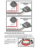
MOPAR Externally Regulated Alternators
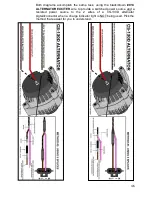
There are two types of external regulators found on these charging systems:
mechanical and electrical.
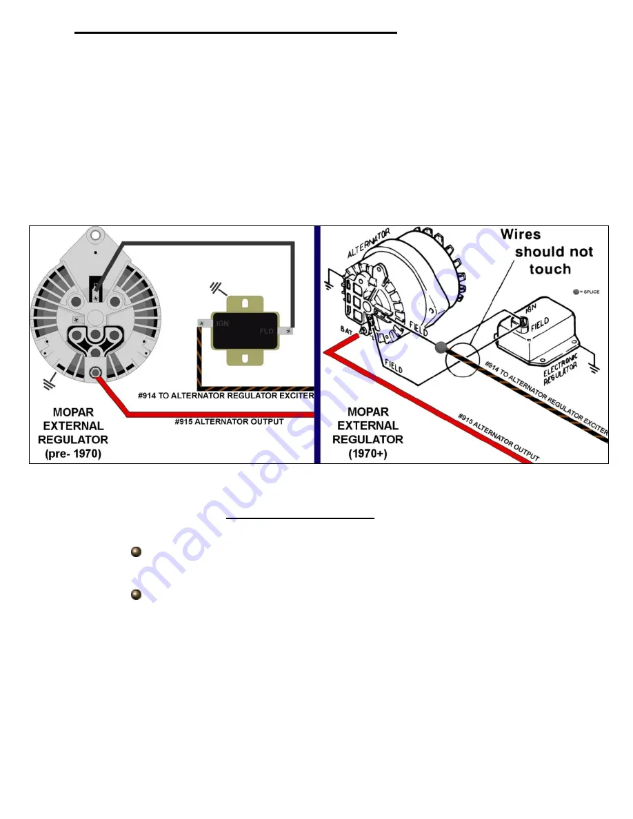
The mechanical regulators, pre-
1970, will have two posts marked “IGN” and
“FLD”. One post will exit one side of the regulator, while the other post will exit the other
side. This regulator will use an alternator that has a single field terminal, as shown in the
“
PRE-1970
” diagram below.
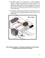
The electrical regulators, 1970+, will also have two posts marked “IGN” and
“FLD”, but both posts will be found on top of the regulator and will require a connector.
This regulator will use an alternator that has two field terminals, as sh
own in the “
1970+
”
diagram below.
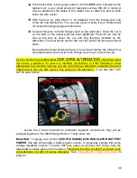
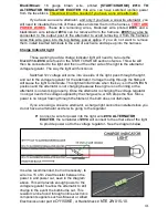
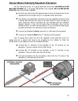
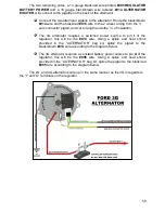
Of the two remaining wires, a 14 gauge black/red wire printed
#995
REGULATOR BATTERY POWER
and a 16 gauge black/brown wire labeled
#914
ALTERNATOR EXCITER
, only the
#914
will be used. The
#995
may be connected to
the alternator output post or removed from the harness.
Route the
#914
wire of the Painless harness to the connection point on
the regulator and cut to length. Strip ¼” of insulation from the wire.
Connect the black/brown
#914
wire t
o the “IGN” terminal on the regulator.
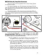
Take notice that on the 1970+ electronic regulator, this
#914
wire will
splice into the wire between the IGN terminal on the regulator and one of
the field tabs on the alternator.
If using an electronic regulator, the two pin connector from a factory
harness will need to be re-used. Due to a lack of usage by most
customers these connectors are not included with this Painless chassis
harness. If you do not have these connectors they can be obtained online
or at a local auto parts store.


