

91
“ACCESSORIES”
This Painless harness includes provisions for several accessory components
which may or may not be used on your particular install. These accessories include
radio, reverse switch, and wiper power. Below you will find information about each of
these accessories and the wires provided in this harness to connect these accessories.
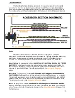
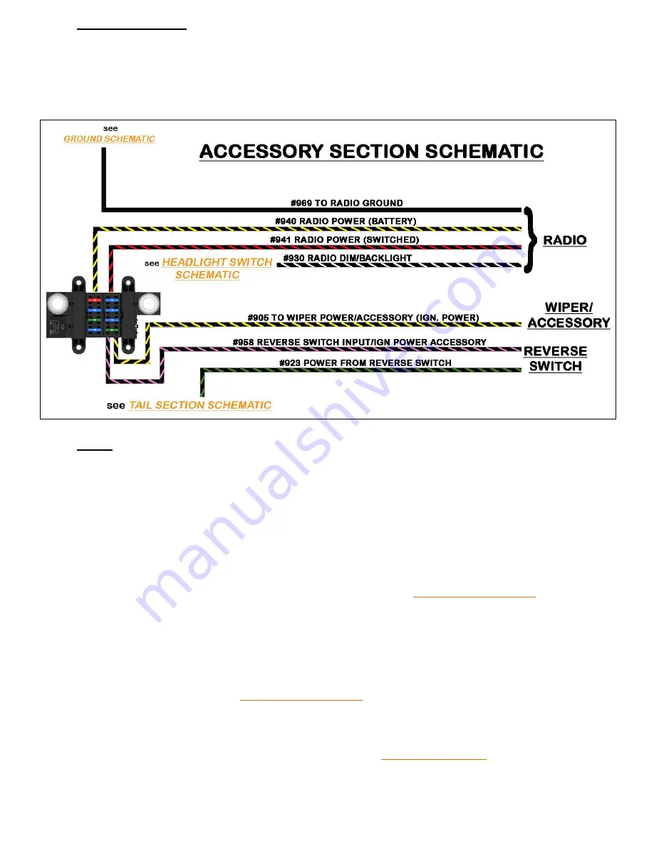
Radio
The radio connection on the Painless harness is set up for a universal
application, meaning, the two power wire colors used by Painless reflect the colors most
aftermarket companies use on radios manufactured today. The Painless harness
includes four wires dedicated for a connection to the radio. These four wires are:
Black/Yellow
: 16 gauge wire, printed
[ACCESSORY SECTION] #940 RADIO POWER
(BATTERY)
, this wire will provide the radio a battery power source that will allow the
time and radio presets to remain every time the ignition is turned off. This wire comes
from the 10 amp RADIO fuse. This wire can be seen in the
Accessory Schematic
above.
Black/Red
: 16 gauge wire, printed
[ACCESSORY SECTION] #941 RADIO POWER
(SWITCHED)
, this wire will provide the radio with ignition switched power for operation.
This wire will have power when the ignition switch is in the ACCESSORY and ON/RUN
positions. This wire comes from the 10 amp RADIO/REVERSE fuse of the fuse block.
This wire can be seen in the
Accessory Schematic
above.
Black
: 16 gauge wire, printed
[ACCESSORY SECTION] #969 TO RADIO GROUND
,
this wire will supply a ground source to the radio. This wire is part of the ground circuit
of the Painless harness. This wire can be seen in the
Ground Schematic
on page 14 of
the first manual.


