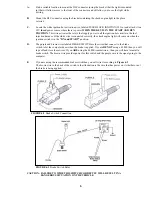
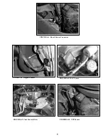
background image

4.2.6


Route the harness away from sharp edges, exhaust pipes, and the hood, trunk and door hinges. 


4.2.7


Plan where harness supports will be located. Use a support approximately every 6 inches unless    


the harness routes under the floor carpet. 


4.2.8


Allow enough slack in the harness at places where movement could possibly occur (body to frame, frame to 
engine, etc.). 


4.2.9


The wires should be bundled into harness groups. Use tape, nylon ties or poly split loom. 


(96-00) Vortec 7.4 Fuel Injection Harness- Part # 60211 


Main Computer  


Service # 16229684 

Idle Air Control Motor   

Delco #217-435 

    Service 

16244210 

Knock 

Sensor 

  Delco 

#213-324 

Brake 

Switch 

  Delco 

#D1565E 

 Coil 

   Delco 

#D577 

Intake Air Temperature   

Delco #213-243   

Cam Position Sensor 


Delco #213-920 

Mass Air Flow Sensor 


Delco #213-252   

Crankshaft Position Sensor 

Delco #213-946 

Engine Coolant Temperature 

Delco #213-310   

VSS (4L80E)  


GM #24203876 

Oxygen Sensor (Drv. Side) 

Delco #AFS93                Oil Pressure Switch                       GM #12553175 

Oxygen Sensor (Pass. Side) 

Delco #AFS 93   

Manifold Absolute 


Throttle Position Sensor   

Delco #213-912   

Pressure Sensor                             Delco #213-351 

Ignition 

Module 

  Delco 

#D579 


Table 4.1

 Compatible Parts For V8 Engines 


5.0 

GENERAL INSTALLATION INSTRUCTIONS 


CAUTION:


DO NOT DISCONNECT THE BATTERY OR THE COMPUTER CONNECTORS WHILE THE 


IGNITION IS ON. 

DO NOT SHORT ANY WIRES IN THIS HARNESS TO GROUND (WITH THE EXCEPTION OF 


LABELED GROUND WIRES) OR DAMAGE TO THE COMPUTER WILL RESULT. 

GIVING OR RECEIVING A "JUMP START" MAY DAMAGE THE COMPUTER. 

DO NOT USE A TEST LIGHT WHEN TESTING COMPUTER SENSORS OR COMPUTER 


CIRCUITS. DAMAGE TO THE COMPUTER WILL RESULT! 

WHEN ROUTING THE WIRES FOR THE VEHICLE SPEED SENSOR (IF USED) MAKE 


CERTAIN THAT THEY ARE AT LEAST 12 INCHES AWAY FROM ANY IGNITION WIRING 


(SPARK PLUG WIRES, ETC.).


Notes:              

There is a normal, small current drain on these fuel injected systems. 

NEVER FORCE ANY CONNECTOR. 

When connecting the plugs to the computer USE EXTREME CARE to make sure none of the pins in  


the computer are or become bent. 

The fuel pump and pressure regulator MUST maintain a constant pressure of 56-62 
PSI (pounds per square inch).  


Summary of Contents for VORTEC 60211

Page 1: ...6 2000 GM VORTEC 7 4 FUEL INJECTION WIRE HARNESS INSTALLATION INSTRUCTIONS Manual P N 90541 Copyright 2005 First Edition AUG 2005 PAINLESS PERFORMANCE PRODUCTS 2501 Ludelle Street Fort Worth Texas 76105 1036 800 423 9696 ...

Page 2: ... CALL PAINLESS WIRING TECH LINE 13 LIST OF FIGURES Figure 6 1 Diagnostic Link Connector DLC Check Engine Light 5 Figure 6 2 Brake Switch Connection 6 Figure 6 3 Brake Switch Relay 6 Figure 6 5 Fuel Pump Relay Connector 7 Figure 6 6 Knock Sensor Connector 9 Figure 6 7 Oxygen Sensors 9 Figure 6 8 MAP Sensor 9 Figure 6 9 CMP Sensor 9 Figure 6 10 CKP Sensor 9 Figure 6 11 Injector Connector 10 Figure 6...

Page 3: ...ransmission is used a stand alone control system is required Usually the computer relays and fuse block can easily be mounted under the dash Most of the wiring in the harness has been pre terminated to the proper connector and all wire has been GM color coded All wiring is TXL 600 volt and 125 degree centigrade with cross link insulation This fuel injection system harness has been divided into thr...

Page 4: ...plied and open not electrically connected when the brakes ARE being applied This is the opposite of a standard brake light switch If you are using a pressure brake switch a SPDT relay must be installed to unlock the converter when the brakes are applied See Figure 6 3 4 2 YOU SHOULD GET TO KNOW THE PARTICULAR ENGINE YOU ARE USING NOTE The 96 00 7 4 had four oxygen sensors from the factory but the ...

Page 5: ... GM 12553175 Oxygen Sensor Pass Side Delco AFS 93 Manifold Absolute Throttle Position Sensor Delco 213 912 Pressure Sensor Delco 213 351 Ignition Module Delco D579 Table 4 1 Compatible Parts For V8 Engines 5 0 GENERAL INSTALLATION INSTRUCTIONS CAUTION DO NOT DISCONNECT THE BATTERY OR THE COMPUTER CONNECTORS WHILE THE IGNITION IS ON DO NOT SHORT ANY WIRES IN THIS HARNESS TO GROUND WITH THE EXCEPTIO...

Page 6: ...NT Note Harness routing and shaping will be a time consuming task Taking your time will enhance the beauty of your vehicle Please take your time and be patient 5 3 1 Permanently mount your computer You should mount the fuse block and relays at this time 5 3 2 Mold harness groups to the contour of the dash engine frame etc Remember to route harness away from sharp edges exhaust pipes hinges and mov...

Page 7: ... Take inventory to see that you have everything you are supposed to have in this kit If anything is missing contact the dealer where you obtained the kit or contact Painless Performance at 800 423 9696 The kit should contain the following items The main wire harness with the connectors already on the ends of most of the wires Fuel Injection Installation Instructions P N 90541 This Booklet 4 7 tie ...

Page 8: ...will come on when the ignition switch is in the ON and START position D The purple and brown wires labeled BRAKE SWITCH are the wires that connect to the brake switch to let the computer know when the brake is applied If you ARE NOT using a 4L80E then you will tape off and store these wires If you ARE using the 4L80E transmission then you will have to install a brake switch The brown wire provides...

Page 9: ...ke Switch Brake Switch White Fuse Block Ignition Ignition Power Table 6 1 Dash Section Connections 6 3 ENGINE GROUP INSTALLATION The engine group is designed to be separated into left side passenger and right side driver sections Each side is tie wrapped separately BUT NOT LABELED The left side of the engine has the connectors for the idle air control and throttle position sensor all of which ARE ...

Page 10: ...ector Wire Colors Black Blue Grey Pink Yellow Black White Yellow Black Tan Black Lt Green Black Lt Blue Black Lt Blue White Lt Green White Pink White Black White White Black Pink White White Black Black White Black Red 2 1 4 4 3 3 3 16 3 3 2 2 4 4 3 Knock O2 SENSOR O2 SENSOR MAP Dist CPS Injector V8 TPS MAF ECT IAT IAC Coil Driver Coil Ground Starter B Knock Sensor Connector Driver Side Oxygen Sen...

Page 11: ...9 FIGURE 6 6 Knock Sensor Connector FIGURE 6 7 Oxygen Sensors FIGURE 6 8 MAP Sensor FIGURE 6 10 CPS Sensor FIGURE 6 9 Cam Sensor Dist ...

Page 12: ...FIGURE 6 12 Coil Driver Component is pictured on a 5 7 This image is used to show connector plug in not component location FIGURE 6 13 TPS Sensor and IAC Valve FIGURE 6 14 Ignition Coil FIGURE 6 15 MAF Sensor FIGURE 6 16 ECT Sensor ...

Page 13: ...e connector for the Vehicle Speed Sensor VSS and connect to the Vehicle Speed Sensor 6 4 4 Take the gray wire labeled FUEL PUMP and route it to the fuel pump This is the power wire for the fuel pump 6 4 5 Tail Section Connections WIRE COLOR OF POSITIONS LABELED CONNECT TO IN CONNECTOR 11 FIGURE 6 17 IAT Sensor Red Black Blue White Purple White Green Black Lt Green Yellow Black Yellow Red Black Lt ...

Page 14: ...GINE LIGHT Normally the check engine light should come on when the ignition is turned on then go out a few moments after the engine starts running If it reappears or stays on while the engine is running the computer has detected a problem and a trouble code has been set NOTE Most likely the check engine light will come on and stay on when using a computer with the original factory programming this...

Page 15: ...nections on the indicated circuit INCLUDING THE COMPUTER are clean and tight Inspect the wiring in the circuit for any broken shorted or exposed wires Finally insure all ground wires are clean and secure 7 2 5 If a trouble code is detected and the problem has been fixed clear the codes by first making sure the ignition is off then disconnecting the NEGATIVE battery cable for at least 3 minutes 7 3...

Page 16: ...d Warranty and Return Policy Chassis harnesses and fuel injection harnesses are covered under a lifetime warranty All other products manufactured and or sold by Painless Performance are warranted to the original purchaser to be free from defects in material and workmanship under normal use Painless Performance will repair or replace defective products without charge during the first 12 months from...

Reviews: