150-450-105-02, Revision 02
Installation
HRE-450 List 5
November 4, 1998
7
4
Do one of the following:
•
If the installation location is wood, use a drill with a wood or metal drill bit to drill the mounting screw
holes into the wooden surface.
•
If the installation location is concrete, use a drill with a concrete drill bit that is slightly smaller than the
diameter of the anchor nuts to drill the mounting screw holes into the concrete surface.
5
Insert the two anchor nuts into the mounting holes and tap the anchor nuts into place with a hammer.
6
While holding the HRE-450 in place, place a washer over one of the mounting-screw holes, then use a #2
screwdriver to screw one of the provided screws into the mounting hole.
7
While holding the HRE-450 in place, place a washer over the other mounting-screw hole then use a #2
screwdriver to screw one of the provided screws into the mounting hole.
W
IRING
THE
HRE-450
The HRE-450 List 5 has two 20-foot air-filled stubs. Each stub is a 6-pair, 24 AWG plastic-insulated, single-
jacketed, air core cable intended for aerial (above ground) applications. Conductors are insulated with solid high-
density polyethylene. Standard color codes are used for pair identification with color compounds chosen for
electrical balance and permanency. A non-hygroscopic core wrap protects the core and provides improved
mechanical electrical characteristics. The cable core shield is a corrugated copolymer coated 8 mil aluminum tape.
The outer jacket consists of a black, low-density polyethylene material that provides a flexible protective covering
that withstands exposure to sunlight, atmospheric temperatures, ground chemicals and stresses expected in
standard installations. The cable complies with the requirements of ANSI/ICEA S-85-625-1989 and REA PE-22.
The outside diameter of the cable is 0.36 inches (9 mm).
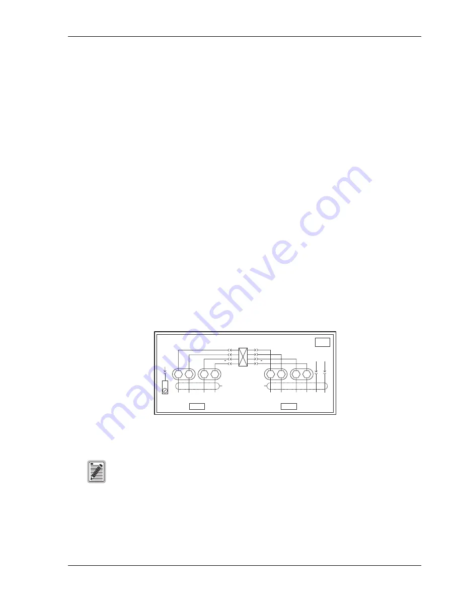
shows the identity of the five ports to which each cable stub provides access. The CO ports are restricted
to the CO HDSL cable pair connections that connect the HRE-450 to either a doubler or a line unit. The field pairs
connect to the DS1 interfaces for remote unit applications.
Figure 4.
HRE-450 Wiring Diagram
The HRU-411 edge connector (inner set of pins) and the mating HRE-450 edge connector
(outer set of pins) have different reference designations for the same pins.
HRE-450 L
FIELD
C.O.
7
1
1
54
27
-
PS
50
25
+
5
C
D
13
15
J
H
41
55
E
Y
47
WHT
ORN
HDSL IN 1
HDSL IN 2
DS1 - RCV
DS1 - XMT
130V
SLT
BLU
RED
BLU
WHT
WHT
WHT BRN
49
C
B
STUB 1
STUB 2
T
T1
R
R1
T
T1
R
R1


