150-458-100-05
Appendix B - Technical Reference
HRE-458 List 1, List 1B, and List 2
February 23, 2000
31
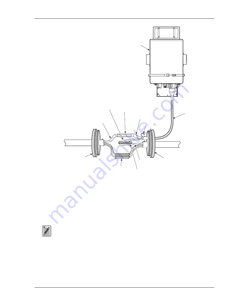
Figure 13.
Dress Splice in Splice Case
Splicing Procedure
1
Splice the cable stub to the main cable using the wire identification information in
and
2
Visually inspect each splice for split pairs, opens, and shorts.
3
Connect the CO side of the main cable to the CO side of the cable stub with a straight splice
(see
4
Once the cables are connected, wrap the CO splice with aluminum tape or dress out the splice according to
local procedures.
5
Connect the field side of the cable stub to the field side of the main cable with a straight splice.
Maintenance personnel sometimes cross-splice defective pairs between units. These pairs are
referred to as “wandering pairs” and may cause problems.
CO splice
Field side
of cable stub
CO side of the
main cable
CO side of the
cable stub
Screen divider
Aluminum
Shielded Cable
with Screen
Divider
Splice Closure
End Plate
Splice Closure
End Plate
Field splice
Field side of
main cable
Main cable out to field
Main cable from CO
Existing Splice
HRE-458


