Section 150-319-254
Revision 02
Page 30
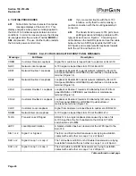
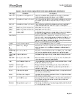
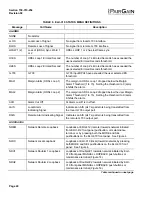
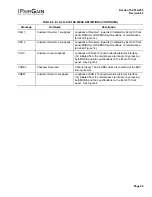
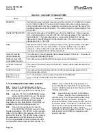
TABLE 10. GLOSSARY OF HIGAIN TERMS
Term
Definition
MARGINS
Indicates the excess signal to noise ratio, at either the ELU-319 or ERU-412, relative
to a 10
-7
Bit Error Rate. 1st value is current margin, 2nd value is minimum margin
since (C)leared last, 3rd value is maximum value since cleared, and NA means Not
Available (loops are not synchronized). The normal range of a typical margin is from
6 to 22 dB.
PULSE ATTENUATION
Indicates the attenuation of the 2B1Q pulse from the distant end. HiGain operates
with pulse attenuations in excess of 30 dB. This value is related to the cable pair’s
loss at 260 kHz. The pulse attenuation is a more direct indication of the loop
attenuation to the 2B1Q signal than the 260 kHz loss. The normal range of pulse
attenuation is from 1 to 32 dB.
PPM
Indicates the relative offset (in parts per million) of the crystal oscillator in the ERU-
412 from the ELU-319’s crystal oscillator. Any value between -64 and +64 is
adequate. Values outside this range indicate out-of- tolerance components or
excessive temperature drift of critical components.
HDSL 24 Hour ES
(Errored Seconds)
The number of 1-second intervals that contained at least 1 CRC error. This value is
a running total of the last 24 hours.
HDSL 24 Hour UAS
(Unavailable Seconds)
The number of seconds the HDSL loop was out of synchronization.
G.703 BPV Seconds
(ES)
The number of seconds during which at least 1 bipolar violation was detected at the
G.703 input.
G.703 UAS Count
The number of seconds during which the G.703 input signal was absent (125 or
more consecutive zeroes).
ELU/Ver x.x-yyyy
ERU/ver x.x-yyyy
“x.x” = the software version number of the ELU-319 or ERU-412.
“yyyy” = the list number of the ELU-319 or ERU-412.
5. SYSTEM MAINTENANCE MENU SCREENS
5.01
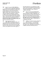
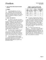
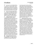
Figure 15 is the Maintenance Terminal
MAIN MENU Screen. Its eight sub-menus provide
many useful provisioning, test and monitoring tools.
5.02
Selection “H” from the MAIN MENU Screen
allows the Circuit ID# to be set. It is limited
to 24 alphanumeric characters. It, like the system
settings, is stored in NVRAM and thus remains
when power is lost. Note that the Circuit ID# is not
available at the ERU-412 Maintenance Port.
5.03
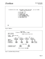
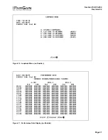
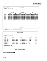
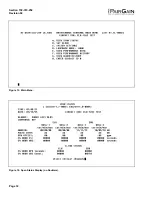
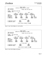
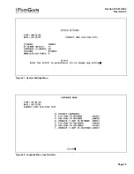
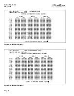
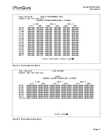
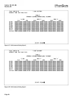
Figure 16 through Figure 19 show the
ELU-319 SPAN STATUS screens for Twin
Doubler applications. The SPAN 1 Screen contains
data on the two HDSL loops between the ELU-319
and the first Doubler. The SPAN 2 Screen refers to
the loops between the first Doubler and the ERU-
412 for single-Doubler circuits or between the first
and second Doublers for two-Doubler circuits. The
SPAN 3 screen refers to the loops between the
second Doubler and the ERU-412 for two-Doubler
circuits. All status screens contain the same G.703
interface information.
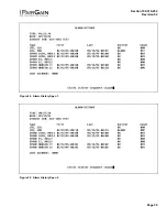
5.04
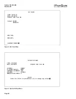
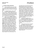
Figure 20 shows the SET CLOCK Menu
Screen. Both the Time and Date are set
with this menu. Set the hours and minutes, using
the military (24-hour) convention. Setting the
seconds is optional. Enter the date in the sequence
and format shown. The ERU-412 unit can be set to
the same time and date as the ELU-319 by entering
a U to the “Update Remote” query. All time
information is lost when power is removed. The last
date is retained in NVRAM and reappears when
power is restored.


