background image

Section 150-319-254

Revision 02

Page 31

5.05

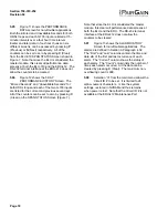
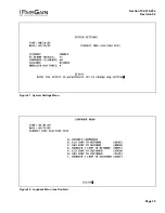
Figure 21 shows the SYSTEM SETTINGS 
Menu Screen.  All 5 user options can be set

from this screen.  To change any option, enter its
character key which is shown inside the parenthesis
within each parameter description.  This causes the
screen to refresh with the new.  After all parameters
have been selected, press E (Exit) then C (Confirm).
The newly selected parameters are now activated.

5.06

Figure 22 shows the LOOPBACK MENU 
Screen for a two-Doubler system.  Each of

the four modules can be looped back towards the
network or the customer from this screen.  NDU2
and CDU2 are not available for single Doubler
applications and only NLOC, NREM, CLOC and
CREM are available for non-Doubler applications.

5.07

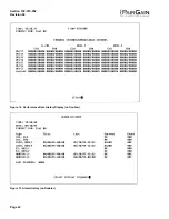
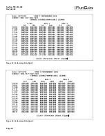
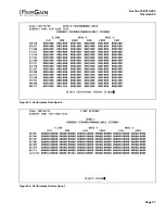
 Figure 23 through Figure 26 show the
PERFORMANCE DATA screens for

Doubler applications.  Both the Errored and
Unavailable Seconds for both HDSL loops and each
G.703 input are listed at 15-minute intervals over a
four hour time interval.  The SPAN 1 Screen
contains data on the two HDSL loops between the
ELU-319 and the first Doubler (EDU1).  The SPAN 2
Screen refers to the loops between the first Doubler
(EDU1) and the ERU-412 for one Doubler circuits or
between the first and second Doublers (EDU1 and
EDU2) for two-Doubler circuits.  The SPAN 3
Screen refers to the loops between the second
Doubler and the ERU-412 for two-Doubler circuits.
All status screens contain the same G.703 interface
errors.  Earlier and later data, in four-hour chunks on
six different screens per span, can be accessed by
pressing P (Previous) or N (Next) respectively.
Performance data from the different spans can be
accessed by entering S (Span).  All of the counters
can be set to “0” by pressing C (Clear) from the
ELU-319 SPAN STATUS Screen shown in Figure
16 through Figure 19.  Note that since the ELU-319
is considered the master module, this clears 

all

performance data screens at both the ELU-319 and
the ERU-412.  The RS-232 terminal interface at the
ERU-412 does not allow the counters to be cleared.

5.08

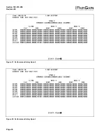
Figure 27 through Figure 30 show the 7-

DAY

PERFORMANCE HISTORY screens for

Doubler applications.  The “Errored Seconds” and
“Unavailable Seconds” for both HDSL loops and
each of the two G.703 inputs are listed for the

current and previous seven days.  The SPAN 1
Screen contains data on the two HDSL loops
between the ELU-319 and the first Doubler (EDU1).
The SPAN 2 Screen refers to the loops between the
first Doubler (EDU1) and the ERU-412 for one-
Doubler circuits or between the first and second
Doublers (EDU1 and EDU2) for two-Doubler circuits.
The SPAN 3 Screen refers to the loops between the
second Doubler and the ERU-412 for two-Doubler
circuits.  All status screens contain the same DS-1
interface errors.  All of the counters can be set to “0”
by pressing C (Clear) on the ELU-319 SPAN
STATUS Screen (Figure 16 through Figure 19).
Note that since the ELU-319 is considered the
master module, this clears 

all

 performance data

screens at both the ELU-319 and the ERU-412.  The
RS-232 terminal interface at the HRU-412 does not
allow the counters to be cleared.

5.09

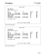
Figure 31 through Figure 33 show the 
ALARM HISTORY screens for Doubler

applications.  The alarms are defined in Section 4
Paragraph 4.01.  The LOS and PWR system alarms
are common to all spans.  Only the LOSW, ES and
MARGIN are span specific alarms.  The PWR-
OPEN and PWR-SHRT alarms indicate alarm
conditions on the ELU-319 List.  Neither PWR alarm
is available on the other spans.  In Figure 31 through
Figure 33, the “First” and “Last” columns contain the
time and date stA of the first and last occurrence of
each alarm.  The “Current” column shows the status
of each alarm.  The “Count” column lists the number
of times each alarm occurred.  All the data can be
cleared by pressing C (Clear).  The maximum non-
overflowing count is 999.  The SPAN 1 Screen
concerns alarms that occurred on the two HDSL
loops between the ELU-319 and the first Doubler
(EDU1).  The SPAN 2 Screen refers to the loops
between the first Doubler (EDU1) and the ERU-412
for one-Doubler circuits or between the first and
second Doublers (EDU1 and EDU2) for two-Doubler
circuits.  The SPAN 3 Screen refers to the loops
between the second Doubler and the ERU-412 for
two-Doubler circuits.

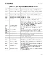
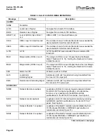
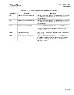
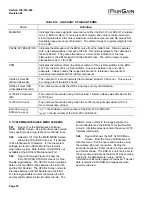
Summary of Contents for ELU-319

Page 1: ...ITHOUT USING HIGAIN DOUBLER EDU 451 11 1 GENERAL 11 2 POWER CONSUMPTION 11 3 LOOPBACK DESIGN DESCRIPTION 12 4 TESTING 13 5 SYSTEM MAINTENANCE MENU SCREENS 17 C APPLICATIONS USING HIGAIN DOUBLER EDU 45...

Page 2: ...s practice Revision 02 February 22 1996 a Numerous updates to tables figures also screen captures to include HiGain Doubler EDU 451 1 03 The ELU 319 is compatible with the PairGain 22 slot HMS 318 she...

Page 3: ...ting ranges on unimpaired cable pairs are shown in Table 2 as a function of cable gauge and average margin 2 05 The ELU 319 List 5D and 6D line units support both one and two doubler applications For...

Page 4: ...G 703 clock at the exact rate received from the remote end The HiGain system operates at G 703 rates of 2 048 Mbps with up to 50 ppm of offset 3 07 A G 703 interface driver converts the G 703 channel...

Page 5: ...at the ELU or ERU G 703 inputs exceeded the 24 hour user selected threshold 7 ALRM MAL1 2 The margin on HDSL Loop 1 Loop 2 has dropped below the Margin Alarm Threshold value set from the Maintenance P...

Page 6: ...Section 150 319 254 Revision 02 Page 6 Figure 3 ELU 319 Pin Outs The active pins are highlighted in black in this illustration...

Page 7: ...after initiation 60 Sets automatic cancellation of all loopbacks to 60 minutes after initiation 120 Sets automatic cancellation of all loopbacks to 120 minutes after initiation ALM Minor Alarm DIS Ret...

Page 8: ...rns to normal display mode If you do not press either button within 30 seconds the parameters return to their original values and the display returns to normal mode 5 05 To set all parameters to their...

Page 9: ...it board as shown in Figure 5 6 02 The factory default setting is unipolar It sets the HDSL line voltage to 0 V on loop 2 and to either 130 V for non doubler applications or 200 V for doubler applicat...

Page 10: ...Line Code 1040 kbps 2B1Q HDSL Output 13 5 dBm 0 5 dB 135 ohms HDSL Line Impedance 135 ohms Line Clock Rate Internal Stratum 4 clock HDSL Startup Time 30 seconds typical 60 seconds maximum One way G 70...

Page 11: ...tive unit freight prepaid along with a brief description of the problem to PairGain Technologies Inc 14402 Franklin Avenue Tustin CA 92680 ATTN Repair and Return Dept 714 832 9922 800 638 0031 11 TECH...

Page 12: ...a MANUAL loopback session This session allows the user to SEL one of four HiGain loopbacks see Figure 5 The message MAN LPBK appears on the front panel display followed by the message NLO If the SEL b...

Page 13: ...r to conserve power the display de energizes after five minutes if neither MODE or SEL are pressed The use of either button restarts the 5 minute power control timer 4 02 If you encounter trouble with...

Page 14: ...1 ACQ 1 or 2 Acquisition 1 or Acquisition 2 The ELU and ERU multiplexers are trying to establish synchronization over each of Loops 1 or 2 of Span 1 H1ES HDSL Loop 1 errored second HDSL CRC error on...

Page 15: ...review mode Press the Mode button for 3 seconds LIST 000X ELU s List Displayed during System Settings review mode defined above LOSW Loss of Sync Word Indicates that one of the HDSL loops has lost sy...

Page 16: ...Off AM Alarm cut off is in effect LAIS Local Alarm Indicating Signal Indicates an AIS all 1 s pattern is being transmitted from the local G 703 output port RAIS Remote Alarm Indicating Signal Indicate...

Page 17: ...conds ES The number of seconds during which at least 1 bipolar violation was detected at the G 703 input G 703 UAS Count The number of seconds during which the G 703 input signal was absent 125 or mor...

Page 18: ...703 inputs are listed for the current and previous seven days All of the counters can be set to zero by pressing C Clear on the SPAN STATUS Screen Figure 7 Note that since the ELU is considered the m...

Page 19: ...Section 150 319 254 Revision 02 Page 19 Figure 6 Main Menu Figure 7 Span Status Display no Doubler...

Page 20: ...Section 150 319 254 Revision 02 Page 20 Figure 8 Set Clock Menu Figure 9 System Settings Menu...

Page 21: ...Section 150 319 254 Revision 02 Page 21 Figure 10 Loopback Menu no Doubler Figure 11 Performance Data Display no Doubler...

Page 22: ...Section 150 319 254 Revision 02 Page 22 Figure 12 Performance Data History Display no Doubler Figure 13 Alarm History no Doubler...

Page 23: ...on density in Watts sq ft 2 03 The thermal loading limitations imposed when using the ELU 319 in Controlled Environmental Vaults CEV or other enclosures are determined by applying the ELU 319 power pa...

Page 24: ...d CLO loopback options in the sequence listed This interactive push button procedure permits any of the eight HiGain loopbacks to be executed activated The next loopback option is presented by pressin...

Page 25: ...Section 150 319 254 Revision 02 Page 25 Figure 14 ELU 319 Doubler Loopback Configurations Each module four in a full two doubler system can be looped back toward either the network or customer...

Page 26: ...buttons or maintenance terminal Figure 14 HDU2 Network Doubler 2 Loopback Loopback at Doubler 2 towards network initiated by ELU 319 front panel MANUAL LOOPBACK push buttons or maintenance terminal Fi...

Page 27: ...r alarm MNRALM condition is in effect 1 xx or 2 yy HDSL Loop Margins Indicates the worst case signal to noise ratio measured for each loop A value of 06 or greater is adequate for reliable system oper...

Page 28: ...hreshold 1 to 15 Setting the threshold to 0 zero inhibits the alarm ACO Alarm Cut Off Al Alarm cut off is in effect LAIS Local Alarm Indicating Signal Indicates an AIS all 1 s pattern is being transmi...

Page 29: ...MANUAL LOOPBACK push buttons or maintenance terminal Figure 14 CLOC Customer Local Loopback Loopback at ERU 412 local towards customer interface CI initiated from the maintenance terminal or by press...

Page 30: ...er of seconds during which the G 703 input signal was absent 125 or more consecutive zeroes ELU Ver x x yyyy ERU ver x x yyyy x x the software version number of the ELU 319 or ERU 412 yyyy the list nu...

Page 31: ...e cleared 5 08 Figure 27 through Figure 30 show the 7 DAY PERFORMANCE HISTORY screens for Doubler applications The Errored Seconds and Unavailable Seconds for both HDSL loops and each of the two G 703...

Page 32: ...Section 150 319 254 Revision 02 Page 32 Figure 15 Main Menu Figure 16 Span Status Display no Doublers...

Page 33: ...Section 150 319 254 Revision 02 Page 33 Figure 17 Span 1 Status Display one or two Doublers Figure 18 Span 2 Status Display two Doublers...

Page 34: ...Section 150 319 254 Revision 02 Page 34 Figure 19 Span 3 Status Display two Doublers Figure 20 Set Clock Menu...

Page 35: ...Section 150 319 254 Revision 02 Page 35 Figure 21 System Settings Menu Figure 22 Loopback Menu one Doubler...

Page 36: ...Section 150 319 254 Revision 02 Page 36 Figure 23 Performance Data Span 1 Figure 24 Performance Data Span 2...

Page 37: ...Section 150 319 254 Revision 02 Page 37 Figure 25 Performance Data Span 3 Figure 26 Performance History Span 1...

Page 38: ...Section 150 319 254 Revision 02 Page 38 Figure 27 Performance History Span 2 Figure 28 Performance History Span 3...

Page 39: ...Section 150 319 254 Revision 02 Page 39 Figure 29 Alarm History Span 1 Figure 30 Alarm History Span 2...

Page 40: ...150 319 254 Revision 02 Page 40 Figure 31 Alarm History Span 3 Copyright 1996 PairGain Technologies Inc PairGain is a registered trademark CopperOptics and HiGain are trademarks of PairGain Technolog...

Reviews: