Section 150-319-254
Revision 02
Page 9
5.10
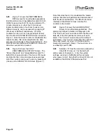
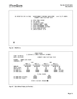
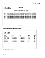
To set the Circuit ID, select H from the Main
Menu to display “Enter circuit ID # (24
characters max)”. Enter the circuit ID, press ENTER,
then press C to confirm the entry. If you enter more
than 24 characters, the terminal beeps and accepts
only the first 24 characters. The circuit ID appears in
all screens, and you cannot reset it to a default as
described in Paragraph 5.05.
5.11
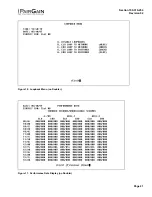
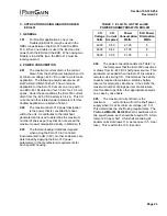
To set the Margin Alarm Threshold, select
G–SYSTEM SETTINGS and then select G–
MAR(G)IN ALM THRES. Enter the minimum
acceptable alarm threshold, from 0 to 15 dB. If the
margin for HDSL Loop 1 or 2 drops
below this value,
the ELU-319 triggers a minor alarm, and the front
panel and status screen displays “MAL1” (Loop 1) or
“MAL2” (Loop 2). Because a margin can never be
less than zero, setting a threshold of zero turns this
feature off.
6. HDSL LINE VOLTAGE OPTION
6.01
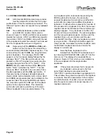
The symmetry of the HDSL line powering voltage
can be set by the S2 switch, located on the printed
circuit board, as shown in Figure 5.
6.02
The factory default setting is unipolar (-). It sets
the HDSL line voltage to 0 V on loop 2 and to
either -130 V (for non-doubler applications) or -200 V (for
doubler applications) on loop 1. This setting keeps the
HDSL cable pair voltage at or below ground potential,
thereby avoiding corrosion problems caused by cable
voltages more positive than ground.
6.03
The bipolar selection sets the HDSL line voltage
to
+65 V on loop 2 and -65 V on loop 1, for non-
doubler applications. Doubler applications will have +100
V on loop 2 and -100 V on loop 1. This setting reduces the
maximum ground referenced voltage to 100 V, but applies
positive voltage to the cable pairs, which could accelerate
corrosion on the cable pairs.
6.04
The line voltage power supply, used for both
options, is ground referenced, but also ground
isolated by 200 kohms. This ground isolation reduces
problems due to induced noise currents and large surge
voltages, which are ground referenced. It also reduces
ground fault currents, which improves the products safety.
The safety issue thus depends solely on the differential
voltage across loop 1 and loop 2, and is independent of
S2s setting.


