Section 150-319-254
Revision 02
Page 13
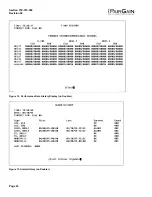
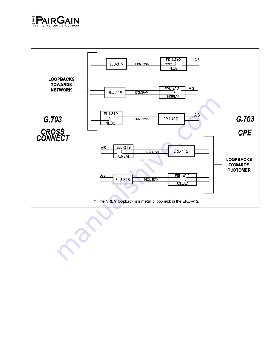
Figure 5. ELU-319 Loopback Configurations. All loopbacks (with the exception of the TLOS logic loopback) can be
initiated from the front panel pushbuttons or from the maintenance terminal.
4. TESTING
4.01
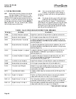
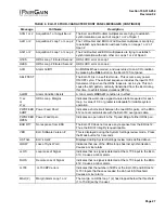
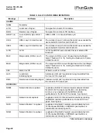
Table 4 lists the four-character front panel
message displays of the ELU-319. This
display energizes when power is initially applied to
the ELU-319; it indicates system status and error
conditions. In order to conserve power, the display
de-energizes after five minutes if neither MODE or
SEL are pressed. The use of either button restarts
the 5-minute power-control timer.
4.02
If you encounter trouble with the G.703
interface, verify that the unit is making a
positive connection with the mounting assembly's
connector.
4.03
The transmit and receive G.703 ports have
splitting access and bridging miniature 210-
type jacks as shown in Figure 2. Connecting one
cable between the two BRG jacks and another cable
between the two SPAN jacks splits the XMT and
RCV jacks and creates metallic loopbacks towards
both the G.703 cross connect and the ELU-319.


