Appendix B - Technical Reference
150-458-100-05
24
February 23, 2000
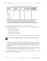
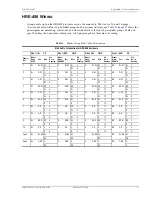
HRE-458 List 1, List 1B, and List 2
Vented-to-Pressurized Conversion Procedure
The following instructions are for converting the HRE-458 List 1, List 1B gel-filled vented enclosure to an
external pressurized enclosure.
The List 1, List 1B enclosure can be converted to a pressurized housing that uses a continuous, local pressure
source. The conversion requires replacing the breather vent valve with an optional external pressure relief valve.
The breather vent valve, located in the base pan, allows the internal pressure to equalize with the outside pressure.
The optional external pressure relief valve is included in the shipping kit. List 1, List 1B comes with a gel-filled
cable which precludes pressurizing through the cable stub.
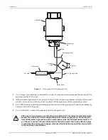
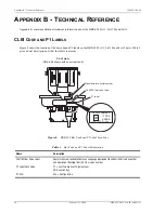
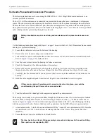
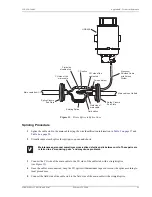
Use the following instructions along with
to convert the List 1, List 1B enclosure from a vented
housing to a pressurized housing:
1
Locate the breather vent valve on the bottom of the housing.
2
Remove the valve by unscrewing it counterclockwise.
3
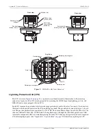
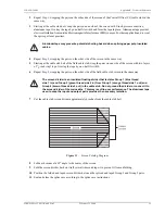
Look inside the valve to confirm that the vent has been removed. The vent contains an internal screen mesh.
Refer to
for further details.
4
Save the vent or store it inside the housing for future conversions.
5
Check the threaded hole for debris and clean it if necessary.
6
Remove the external pressure relief valve from the plastic bag. Verify that an O-ring is installed on the
threaded end of the valve and on the brass fitting in the base of the enclosure for a total of two O-rings.
7
Carefully place the threaded end of the air pressure relief valve into the threaded hole on the bottom of the
housing.
8
Hold the valve straight and push it into the hole. Begin to turn it clockwise to screw it in place.
9
Turn the valve until it is handtight with compression against the gasket material.
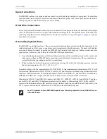
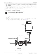
The housing is now ready to be pressurized either through the Schrader air stem valve which accepts a standard
tire valve chuck or through the external air inlet stem using a feeder tube with a
1
/
2
”/24 thread connection, as
shown in
. A two-unit desiccant bag is also included in the List 1, List 1B shipping kit along
with the pressure relief valve. Remove the desiccant bag and place it in the HRE-458 prior to pressurization.
1
Attach a plastic tube,
1
/
4
-inch (.64 cm) inner diameter (ID) by
3
/
8
-inch(.83 cm) outer diameter (OD), from the
external air source to the
1
/
4
-inch (.64 cm) air intake protrusion of the T-valve. (The plastic tube is not
included.)
2
Secure the tube to the valve with the hex bolt and ferrule.
Static pressurization requires monitoring and maintenance as the pressure decreases over
time.
If there are any signs of resistance while screwing the valve into place, you could be
crossthreading the part. Remove the valve and restart.
The tube, hex bolt, and ferrule fitting assembly is also called an Express Air Connection Fitting.
These parts are not supplied by ADC.

