
150-458-100-05
Appendix B - Technical Reference
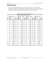
HRE-458 List 1, List 1B, and List 2
February 23, 2000
33
2
Repeat
, wrapping the pairs on the other side of the screen of the Central Office (CO) cable stub in the
same way.
3
Starting at the cable stub butt, wrap the pairs on one side of the screen with 2-inch, pressure sensitive,
aluminum tape. Overlay the tape by one-half its width and form the tape in place. Aluminum tape provides
electrical isolation from outside Electromagnetic Interference (EMI) sources. For these applications, dress out
the splice per local practices.
4
Repeat
, wrapping the pairs on the other side of the screen in the same way.
5
Starting at the cable stub butt of the field cable stub, wrap the pairs on one side of the screen with two layers
of
3
/
4
-inch vinyl tape. Overlap the tape by one-half its width.
6
Repeat
, wrapping the pairs on the other side of the field cable stub screen in the same way.
7
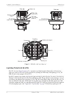
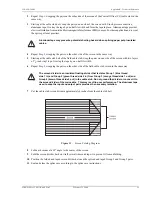
Cut the cable stub screen divider approximately 6 inches from the cable stub butt.
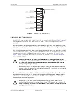
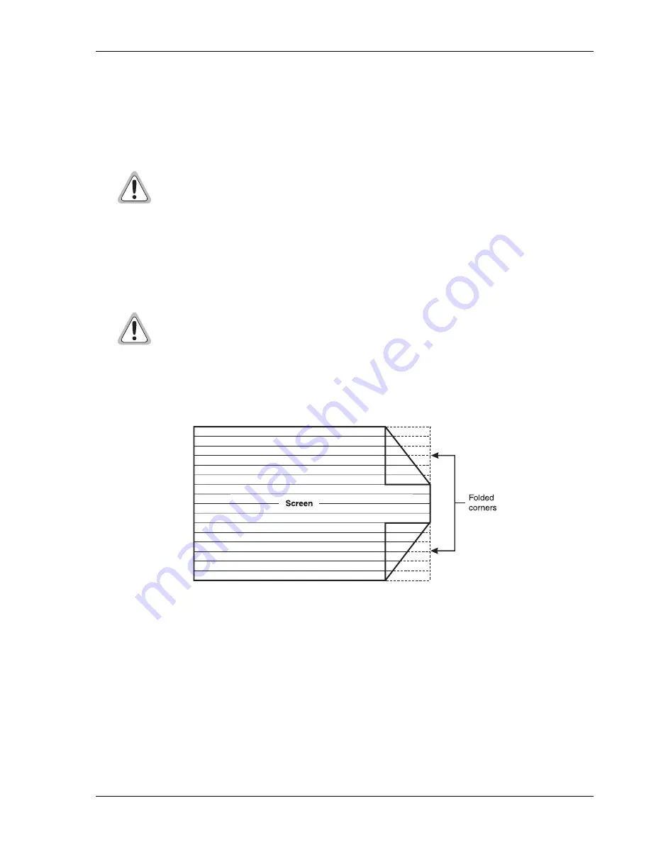
Figure 15.
Screen Folding Diagram
8
Fold each corner at a 45° angle to the center of the screen.
9
Fold the screen divider back on itself several times and tape it to prevent it from unfolding.
10 Position the folded and taped screen divider between the spliced and taped Group 1 and Group 2 pairs.
11 Seal and close the splice case according to the splice case instructions.
Aluminum tape may present a potential shorting hazard when splicing paper pulp insulated
cables.
The screen divider is an insulated floating divider that isolates Group 1 (blue thread
side 1 in) and Group 2 (green thread side 2 in) from Group 3 (orange thread side 1 out) and
Group 4 (brown thread side 2 out) in the cable stub. Do not ground the divider or connect it to
the screen divider of the main cable. This may result in poor performance. The aluminum tape
used to wrap the input and output pairs provides the necessary isolation.


