150-458-100-05
Appendix B - Technical Reference
HRE-458 List 1, List 1B, and List 2
February 23, 2000
21
HRE-458 E
NCLOSURE
I
NFORMATION
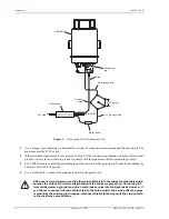
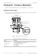
Both the List 1, List 1B, and List 2 units have access to an order wire pair shown in
(List 1,
List 1B) and
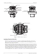
(List 2). The enclosure mounting plate (see
) allows the unit
to be tilted 31° from its vertical position. This reduces the headroom, required in manhole installations, from 10
inches to 3 inches and the amount of valuable air space, required for such underground applications.
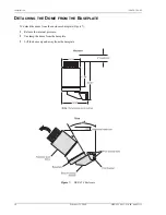
Stainless-steel Therm-O-Nator Dome
A stainless steel dome cover fits over the card cage and protects the enclosure from heat and other harmful
environmental effects. The dome seals the inner assembly, when clamped to the baseplate, providing a seamless,
corrosion-resistant, easily-removed protective cover. The stainless steel cover V-retainer, which is equipped with
a T-bolt, is used to tighten the dome firmly against the O-ring on the baseplate. The purpose of the O-ring is to
create a pressure-tight seal between the dome and the baseplate. There is also a locking cover over the T-handle
which prevents unauthorized access to the enclosure. This cover accepts a padlock with a maximum shackle
diameter of 0.3-inch (0.76 cm). The V-retainer T-bolt should be torqued between 10 and 15 inch-pounds for
proper sealing.
A special heat exchange assembly is attached to the top lid of the dome. The assembly allows internal heat
produced by the units to quickly expel into the outside atmosphere before overheating occurs. This heat reduction
also allows the enclosure doubler capacity to increase.
Card Cage
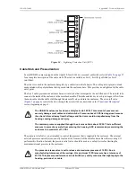
The card cage inside the enclosure (shown in
) has ten mounting positions to hold up to ten
doubler units. The cage also has a retainer bar which serves two purposes:
•
The circuit ID of each slot can be written on the label attached to each retainer bar.
•
The retainer bar prevents the doubler units from disconnecting when the enclosure is subjected to severe
vibrations.
You can access the doubler units by loosening the side wingnuts and rotating the retainer bar. The enclosure has
a mechanism that enables the card cage to tilt up approximately 45° to allow for easy access to the rear of the card
cage in case LPU board service is needed. Two knobbed retainer screws at the base of the card cage (one on each
side) lock the card cage in its normal level position and prevent it from tilting during severe vibrations. The cable
stub’s shield is grounded to the card cage base through a short braided wire. This braided wire should be
disconnected if the enclosure stub’s shield is bonded to the shield of the main feeder cable. This will break the
ground loop, created by connecting the two cable shields, and prevent circulating ground currents from possibly
causing service affecting noise.
The card cage is grounded through a ribbon ground connected between the base of the card cage and its side.

