background image

Revision 01

February 24, 1998

Section 363-712-131-01

PG-Flex FLL-712 List 3A

PairGain Engineering - Plant Series

Page 5

B.  FUNCTIONAL DESCRIPTION

4.  Applications

4.1

Overview.  

PG-Flex is a small-capacity, universal subscriber carrier system supporting up to

24 DS0 channels including both Plain Old Telephone Service (POTS) and Integrated Services Digital
Network (ISDN) services.  The system is based on HDSL transmission technology.  Remote power is
supplied from the Central Office (CO).

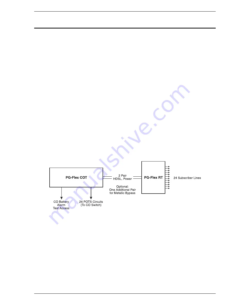
A PG-Flex system is comprised of one line unit and one (or more) channel units at both the CO and
the RT (Figure 2).  Line units and channel units can be hot-swapped without affecting other systems
in the same shelf.  The POTS channel units use a Pulse Code Modulation (PCM) encoding scheme
that allows high speed modem and group 3 facsimile operation on all channels.

The CO-side of a PG-Flex system mounts into a COT shelf and supports up to four systems.  An
alarm unit or Pair Gain Test Controller (PGTC) interface unit (common to all systems installed in the
shelf) provides an interface for maintenance alarm relays and metallic access to the remote
subscriber lines.

The remote side of a PG-Flex systems mounts into an FRE-765 RT enclosure.  The RT enclosure
supports one system, which includes one line unit and up to three channel units.  The channel units
must be the same type of card as the channel units installed at the CO.

PG-Flex uses HDSL transmission technology over two unconditioned copper pairs.  Power is
supplied from the CO to the RT over the HDSL transmission lines.  The maximum distance from the
CO to the RT is 12.3 kft (3.7 km) using 24 AWG cable (0.5 mm).

Figure 2.  Typical PG-Flex Configuration

4.2

HDSL Transmission.

  PG-Flex uses HDSL transmission technology between the COT and RT.

This technology provides up to 24 DS0s, plus signaling, over two copper pairs without using
repeaters, loop conditioning, or pair selection.  Adaptive equalization, scrambling, and a four-level
2B1Q line coding scheme increase range and minimize crosstalk.

The line interface is a two-pair, 784-kbps full-duplex 2B1Q transmission format.  The dual HDSL
lines provide 24 channels at 64-kbps, with signaling and an operations channel for management
control. The signal characteristics on the carrier pairs comply with TR-NWT-001210, Generic
Requirements for High-bit-rate Digital Subscriber Line (HDSL) Systems.

Summary of Contents for PG-Flex FLL-712

Page 1: ...NIT Model List Number Part Number CLEI Code FLL 712 3A 150 1312 31 VACHDFLCAA PAIRGAIN TECHNOLOGIES INC ENGINEERING PLANT SERIES TECHNICAL PRACTICE SECTION 363 712 131 01 Revision History of this practice Revision 01 February 24 1998 A Initial Release ...

Page 2: ...Abbreviations 42 15 Glossary 42 USING THIS TECHNICAL PRACTICE Two types of messages identified by icons appear in the text A note informs you of special circumstances Cautions indicate the possibility of damage to equipment or the possibility of personal injury Copyright 1998 PairGain Technologies Inc PairGain is a registered trademark and PG Flex is a trademark of PairGain Technologies Inc Inform...

Page 3: ...ASCII terminal The FLL 712 COT line unit uses PairGain s High bit rate Digital Subscriber Line HDSL 2B1Q technology to provide the equivalent of 1 544 Mbps digital transmission rates plus signaling over two copper pairs The HDSL line can include unterminated bridge taps The technology is implemented without using repeaters without loop conditioning without pair selection The FLL 712 supports the u...

Page 4: ...01 Page 2 PairGain Engineering Plant Series PG Flex FLL 712 List 3A 2 Front Panel Figure 1 shows the FLL 712 line unit front panel Table 1 lists the indicators and indicator states for the FLL 712 front panel LEDs Figure 1 FLL 712 List 3A Front Panel ...

Page 5: ...sync with remote unit OFF HDSL line 1 does not detect an active remote unit LOOP 1 MARGIN Solid Yellow HDSL line 1 is below preset margin threshold OFF HDSL line 1 margin is above the preset margin threshold LOOP 2 SYNC Solid Green HDSL line 2 is in sync between the COT and RT Flashing Green HDSL line 2 is attempting to sync with remote unit OFF HDSL line 2 does not detect an active remote unit LO...

Page 6: ...put Power 145 Watts maximum COT Power Supply Input Protection Fuse 3A GMT COT Power Supply Output Voltage 130 Vdc maximum COT Power Supply Output Power 100 Watts maximum Environmental Operating Elevation 200 ft to 13 000 ft 60 m to 4 000 m Operating Temperature Humidity 40 F to 150 F 40 C to 65 C 5 to 95 non condensing Physical Dimensions Height 6 7 in 17 2 cm Width 2 0 in 5 1 cm Depth 10 5 in 26 ...

Page 7: ...relays and metallic access to the remote subscriber lines The remote side of a PG Flex systems mounts into an FRE 765 RT enclosure The RT enclosure supports one system which includes one line unit and up to three channel units The channel units must be the same type of card as the channel units installed at the CO PG Flex uses HDSL transmission technology over two unconditioned copper pairs Power ...

Page 8: ...t is switched to the test jack on the FAU 728 or FPI 729 units or to the corresponding subscriber line on the COT channel card Metallic access is performed by momentarily placing 116 Vdc from the CO on the subscriber s Tip lead The Ring lead should be between GND and the Tip value With POTS Ground Start Loop Start and ISDN channel cards the selected subscriber drop assuming a working metallic bypa...

Page 9: ...CO battery into voltages necessary to power the PG Flex electronics including 130 Vdc During power up the system checks the HDSL lines for hazardous voltages or other line faults that may effect the system If a fault condition is detected the system stops the power up sequence and the LED indicators on the front panel indicate a line fault problem Figure 3 FLL 712 COT Line Unit Block Diagram ...

Page 10: ... the subscriber circuit monitor system performance obtain an inventory report 6 2 Connecting FLL 712 to a Terminal or Modem Figure 4 shows the pinouts for connecting the FLL 712 Craft port to an ASCII terminal The FLL 712 line unit will not automatically log off when a terminal is unplugged from the craft maintenance port unless the DTR signal is connected between the terminal and the Craft port T...

Page 11: ...ect CD override This causes the modem to send CD signal when it connects with another modem and to drop CD when it disconnects Otherwise if set ON the FLL 712 connection functions correctly but does not log out when disconnected It is recommended that Data Terminal Ready DTR override be OFF This allows a modem call to terminate correctly when the FLL 712 drops DSR which is null modemed to DTR inpu...

Page 12: ...y 24 1998 Revision 01 Page 10 PairGain Engineering Plant Series PG Flex FLL 712 List 3A 6 3 Menus and Display Structure Figure 6 shows the menu structure of the terminal management system Figure 6 Terminal Menu and Display Structure ...

Page 13: ...splays a log on screen when it detects user input from the Craft port while idle 1 Press the Spacebar rapidly several times to start the autobaud feature autobaud supports transmission rates of 1 200 2 400 4 800 and 9 600 bps only This input causes the log on screen to display 2 Enter your password For security reasons the password input is echoed with characters If you do not have your logon pass...

Page 14: ...or after the power has been turned off Enter the new system time in hours HH minutes MM and seconds SS This screen will not appear the next time you log on unless the power has been turned off 6 7 Main Menu From the Main Menu you access other menus where you can configure a PG Flex system initiate or view test procedures and view status information The Main Menu is displayed after a successful log...

Page 15: ...the HDSL span You can view either a 24 hour or 7 day performance history Alarm History to display the status history of COT RT and span alarms ISDN Performance Monitoring Menu to show PM error count and PM threshold for a specific ISDN card and channel B Setup Select the Setup option B from the Main Menu to view the current setup or to set or change the following configurable items System Setup Ti...

Page 16: ...erface Unit or an FAU 728 List 2 Alarm Unit must be installed at all times when ISDN channel units are installed These units provide the composite clock reference source for the ISDN channel units and are required for normal operation of the ISDN channel units Removing the FPI 729 List 1 or FAU 728 List 2 during an ISDN call terminates the call 8 1 Install a FLL 712 COT line unit and verify operat...

Page 17: ...he following voltages on the COT shelf backplane 130 Vdc 10 between the HDSL_T1 pin and chassis ground 0 Vdc to 130 Vdc between the HDSL_T2 pin and chassis ground 9 Provisioning 9 1 Configure System Settings Perform system setup if not previously accomplished 1 Type B then press Enter at the Main Menu The Setup Menu is displayed ...

Page 18: ... 2 Type A then press Enter The System Settings menu is displayed 3 Type a letter A through N and press Enter to select a parameter to change Refer to Table 4 for system settings menu options You get a separate screen for the parameter selected It prompts you to input the change 4 Type Ctrl X to return to the Main Menu ...

Page 19: ...e System ID is supplied to indicate the physical location of the PG Flex system CO or RT terminal Each PG Flex system should have a unique System ID The default for System ID is blank all spaces This can be left blank or set to any desired name of 24 or fewer characters including spaces This name can be any mixture of alphanumeric characters including upper case lower case numerals punctuation etc...

Page 20: ...inutes 60 Automatically logs out after 60 minutes F Metered Tone Frequency 12 Metered tones are used for out of band signaling with coin telephones typically in international markets A special channel card is required to support this function G Ring Frequency 20 Determines the frequency of the ringing voltage on the subscriber line The values can be set to one of the following parameters 20 The ri...

Page 21: ... can be set to one of the following parameters DISABLED A minor alarm does not occur when the HDSL ES Alarm Threshold and or HDSL Margin Threshold is exceeded ENABLED A minor alarm occurs when the HDSL ES Alarm Threshold and or HDSL Margin Threshold is exceeded K Local Loop Length Long The length of subscriber loop supported by PG Flex is determined by this parameter and affects all subscriber loo...

Page 22: ...ch of channel units M Alarm on Insufficient Time Slot DISABLED This parameter determines whether a minor alarm is generated if more circuits have been enabled than there are time slots available This could occur when enabling ISDN circuits without first disabling a sufficient number of POTS circuits to ensure that there are enough time slots available to support the ISDN circuits The values can be...

Page 23: ...et up the ISDN module starting from the Setup Menu 1 Type E then press Enter to view the ISDN Channel Setup selection menu If there are no ISDN cards present in your PG Flex system the display will indicate that there are no ISDN cards installed and not allow you to continue to the ISDN Channel Setup menu 2 Type the card number followed by a comma then type the channel number and press Enter for t...

Page 24: ...ded and are passed through the PG Flex system transparently C B1 B2 Swap This parameter determines whether the B channels are swapped between the PG Flex CO ISDN U interface and the RT ISDN U interface The D signaling channel is unaffected by this parameter Normal ISDN channel B1 and B2 at the CO ISDN U interface are routed to channels B1 and B2 at the RT ISDN U interface Swap ISDN channel B1 and ...

Page 25: ... disable a channel or type E to enable a channel and then press Enter You get a prompt to enter the card and channel number 4 At the prompt for the system to be configured enter the card number followed by a comma and then enter the channel number and press Enter that is type 1 1 for card 1 on channel 1 Table 6 Channel Configuration Options Parameter Default Value Function Channel Configuration EN...

Page 26: ...f required by local practice start at the Setup Menu 1 Enable disable the Alarm On ISDN PM Threshold Cross a Type A then press Enter to display the System Settings menu b Type N then press Enter to display the Alarm On ISDN PM Threshold Cross menu c Type Y then press Enter to enable the alarm or type N then press Enter to disable the alarm ...

Page 27: ...eering Plant Series Page 25 9 2 4 View time slot assignments starting at the Setup Menu Type B then press Enter to display the Time Slot Assignment menu These values are automatically generated However when you cycle power to the system or hot plug a new channel unit these values can change ...

Page 28: ...N cards present in your PG Flex system the display will indicate that there are no ISDN cards installed and not allow you to continue to the ISDN Channel Setup menu 2 Type the channel unit number followed by a comma then type the channel for the new ISDN channel unit That is type 2 3 for ISDN card number 2 on channel 3 3 Type a letter B or C and press Enter to view status for the channel unit and ...

Page 29: ...rough 9 3 4 Some screens can be different when channel units are installed in a 19 inch or 23 inch shelf A 19 inch shelf has two systems where each has from one to six channel units A 23 inch shelf has four systems where each has from one to three channel units The example screens where appropriate show only a 23 inch shelf with three channel units 9 3 1 Set up the channels for loop start or groun...

Page 30: ...n Menu 3 Type L then press Enter to change the channel to loop start or type G then press Enter to change the channel to ground start You get a prompt to enter the card and channel numbers 4 At the prompt type the card number followed by a comma and then type the channel number for the channel unit and channel you want to disable enable then press Enter that is type 1 1 for card 1 on channel 1 ...

Page 31: ...able is the default for the channels Disable channels only when the time slots are required by another channel unit 1 Type C then press Enter to display the Channel Configuration menu 2 Type D disable or E enable then press Enter You get a prompt to enter the card and channel numbers 3 At the prompt type the card number followed by a comma and then type the channel number for the channel unit and ...

Page 32: ...e Setup Menu Type B then press Enter to display the Time Slots Assignment menu These values are automatically generated However when you cycle power to the system or hot plug a new channel unit these values can change 9 3 4 Test the loop start and ground start channels 1 Verify that front panel ACTIVE indicators are OFF and FAULT indicator is off 2 Test circuits for loop start 3 Test circuit for g...

Page 33: ...ineering Plant Series Page 31 9 4 View Doubler Status Paragraphs 9 4 1 through 9 4 2 provide steps for viewing the status of a doubler unit s 9 4 1 View status for the doubler unit s through the HDSL Status menu 1 Starting at the Main Menu type A then press Enter to display the Status Menu ...

Page 34: ...performance history B Shows a 7 day performance history CTRL X Exits the current screen and returns to the Main Menu R Resets minimum and maximum margins 24 Hour ES 24 Hour UAS and 24 Hour Performance History A prompt has you type Y to confirm the reset or type N to cancel the reset X Exits this screen and returns to Status Menu S Shows doubler spans not seen on the current screen The first screen...

Page 35: ...01 PG Flex FLL 712 List 3A PairGain Engineering Plant Series Page 33 9 4 2 View status for the doubler unit s through the alarm history menu by completing the following 1 Type D then press Enter at the Main Menu The System Alarm History menu displays ...

Page 36: ...nt Series PG Flex FLL 712 List 3A 2 Type C then press Enter at the Main Menu The Alarm History menu displays 3 Type S then press Enter to get the additional screens for the doubler spans The following Alarm History menu Span 2 is only available when a doubler is present in the circuit ...

Page 37: ...cribes the steps for testing a circuit using the metallic access options and paragraph 9 5 2 describes the steps to initiate an ISDN loopback test Type C then press Enter from the Main Menu to access the Maintenance Menu 9 5 1 Metallic Access A metallic access connection to a subscriber circuit can be setup using the metallic access options 1 From the Maintenance Menu type A then press Enter The M...

Page 38: ...ability to stimulate the subscriber connection through the CO channel unit The switch is disconnected from PG Flex for this function D RT Looking In Provides the ability to monitor the subscriber circuit at the RT channel unit Tip Ring pair with the subscriber terminal equipment disconnected E RT Looking Out Provides the ability to verify the channel the subscriber drop off with the RT channel uni...

Page 39: ...criber circuit being tested Metallic access to the selected circuit is provided at the test jack on the FPI 729 or FAU 728 front panels b Use a VOM Butt in or other test equipment to test the subscriber circuit c At the prompt for the system to be accessed enter the card number followed by a comma and then enter the channel number 9 5 1 2 To release a subscriber drop select R then press Enter ...

Page 40: ...opback from the Maintenance Menu b Select C from the ISDN Loopback Menu c Select the card and channel to be tested d Select the Loopback type desired In most instances a loopback of the B1 or B2 channels towards the office DSL or customer DC is sufficient to verify operation of the ISDN circuit 9 5 2 2 To release Loopback on an ISDN line a Select Change Loopback Mode from the ISDN Loopback Menu b ...

Page 41: ...ignal from the remote terminal line unit This is usually an indication that there is a problem with the HDSL circuit between the COT and RT assuming the FAULT LED is off Verify the HDSL circuits are terminated properly and with the correct orientation Measure the loop resistance of each HDSL circuit shorting the pair at the far end The loop resistance must be less than that shown in Table 2 2 The ...

Page 42: ...istance calls are normally answered directly by a Customer Service Engineer At other times a request for technical assistance is handled by an on duty Customer Service Engineer through a callback process This process normally results in a callback within 30 minutes of initiating the request 11 3 In addition PairGain maintains a computer bulletin board system for obtaining current information on Pa...

Page 43: ... the provisions in the current edition of the National Electrical Code 13 Warranty 13 1 PairGain Technologies warrants this product to be free of defects and to be fully functional for a period of 5 years from the date of original shipment given proper customer installation and regular maintenance PairGain will repair or replace any unit without cost during this period if the unit is found to be d...

Page 44: ... 22 to 6 dB Pulse Attenuation Indicates the attenuation of the 2B1Q pulse from the distant end PG Flex operates with pulse attenuations in excess of 30 dB This value is related to the cable pair s 196 kHz loss The pulse attenuation is a more direct indication of the loop attenuation to the 2B1Q signal than the 196 kHz loss The normal range of pulse attenuation is from 1 to 32 dB PPM Indicates the ...

Page 45: ...Revision 01 February 24 1998 Section 363 712 131 01 PG Flex FLL 712 List 3A PairGain Engineering Plant Series Page 43 ...

Page 46: ......

Reviews: